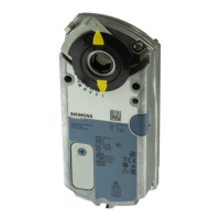
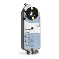
OpenAir Non-Spring Return Rotary Electric Damper Actuator Technical Instructions
24 Vac Floating Control Document No. 155-188P25
December 26, 2007
Siemens Building Technologies, Inc. Page 7
You must place the actuator on the damper shaft so that the front of the actuator is
accessible. The label is on the front side.
The minimum damper drive shaft length is 3/4-inch (20 mm).
EA1002R1
Mounting and
Installation
1/2 Ø inch Guide
Factory Installed
3/8 Ø inch
Use shaft insert supplied
for any 3/8-in (8 - 10 mm)
diameter shaft
5/8 Ø inch
NOTE: For all damper shafts with the exception of the 1/2-inch round shaft:
Remove 1/2 Ø inch guide before installation.
Figure 14. Damper Shaft Sizes.
A mounting bracket is included with the actuator.
Observe the service envelope around the actuator as shown in Figure 25.
Detailed mounting instructions are included with each actuator.
Manual override
To move the damper blades and lock the
position with no power present:
1. Slide the red manual override knob
toward the back of the actuator.
2. Make adjustments to the damper
position.
3. Slide the red manual override knob
toward the front of the actuator.
Once power is restored, the actuator returns
to automated control
.
45
90
90
PL0013R2
MANUAL
ADJUSTMENT
LEVER
AUTO
2
1
3
Figure 15. Manual Override.
Mechanical range
adjustment
1. Loosen the stop set
screw.
2. Move the screw along
the track to the desired
position, and fasten it in
place.
45
90
90
EA0535R2
4 mm
45¡
90¡
90¡
EA0536R2
<
90¡
Figure 16. Moving the Mechanical Range Stop.
1
2
 Loading...