Do you have a question about the Siemens OpenAir GEB 1 Series and is the answer not in the manual?
| Brand | Siemens |
|---|---|
| Model | OpenAir GEB 1 Series |
| Category | Controller |
| Language | English |
Records of changes and dates for document revisions.
Defines target audience, purpose, and scope of the technical basics document.
Lists the topics covered in the document for GEB...1 actuators.
Details the use cases for actuators in ventilating and air conditioning systems.
Presents a table summarizing features and options for various actuator types.
Explains the functions of GEB...1 actuators based on control types.
Assigns functions to specific control types such as three-position and modulating.
Provides additional details on functions for GEB16..1 modulating actuators, including self-adaptation.
Identifies compatible controllers and their output signals for GEB...1 actuators.
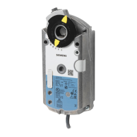
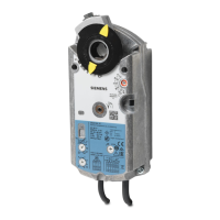
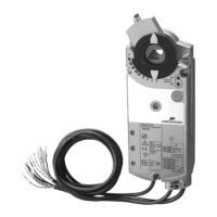
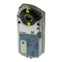
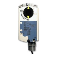
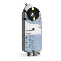
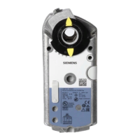
Describes the physical construction, housing, and key elements of the electronic actuators.
Details actuator controls, DIL switches, potentiometers, and shaft adapter arrangements.
Explains the synchronous motor and magnetic coupling for precise speed control and torque supervision.
Illustrates the relationship between mechanical limits and the actuator's rotary range.
Shows how rotary angle relates to auxiliary switch points and positioning signals.
Guides on setting offset and span for modulating actuators using potentiometers.
Defines the neutral zone and hysteresis for modulating control characteristics.
Covers general and system-specific regulations for voltages and essential safety warnings.
Addresses regulations for actuators concerning electrical safety, connections, and handling.
Provides guidance on minimizing electromagnetic interference during cable installation.
Explains how to calculate required torque and select the appropriate actuator type.
Guides on determining line length and cross-section based on power consumption and voltage drop.
Details wiring for three-position actuators, particularly for AC 24 V supply.
Provides wiring information for modulating actuators, including AC supply and positioning signals.
Outlines wiring procedures for actuators employing Modbus RTU communication.
Specifies checks for environmental conditions, mechanical settings, and electrical connections.
Describes procedures to verify actuator operating states, movement, and functionality.
Covers Modbus communication protocols for actuators.
Explains the actuator's push button and LED interface for Modbus operations.
Details how to set Modbus addresses using the push button and LED interface.
Outlines the workflow for commissioning actuators, including bus configuration.
Lists and explains Modbus registers for process values and parameters.
Describes key actuator functions like override control, adaptive positioning, and reset.
Presents internal circuit diagrams for three-position and modulating actuator types.
Provides color coding and labeling standards for actuator connection wires.
Illustrates wiring diagrams for connecting three-position actuators to control systems.
Shows wiring diagrams for modulating actuators, including typical application scenarios.
Describes the standard connection of controller output directly to the actuator input.
Explains how to achieve different operating states via switch contacts for modulating control.
Presents connection diagrams for networked actuators utilizing bus cables.
Details connecting the application controller to the actuator through a bus cable.
Provides technical drawings and measurements for actuator dimensions and mounting bracket.
Lists all documents referenced within the manual for technical basics and accessories.
