EasyManua.ls Logo

Siemens OpenAir GLB 1E Series - User Manual

Siemens OpenAir GLB 1E Series
10 pages
Print Icon
To Next Page IconTo Next Page
Loading...
A6V10636202_enAP_c Siemens
2018-01-25 Building Technologies
OpenAir™
Air damper actuators
GLB..1E
Electronic motor driven actuators for open-close, three-position
and modulating control
Nominal torque 10 Nm
Operating voltage AC 24 V ~ / DC 24…48 V or AC 100…240 V ~
Mechanically adjustable span between 0...90°
Pre-wired with 0.9 m long connection cables
Type-specific variations with adjustable offset and span for
the positioning signal
Position indication: mechanical and electrical
Feedback potentiometer
Self-adaption of rotational angle range and adjustable auxiliary switches for
supplementary functions
30
s
Question and Answer IconNeed help?

Do you have a question about the Siemens OpenAir GLB 1E Series and is the answer not in the manual?

Overview

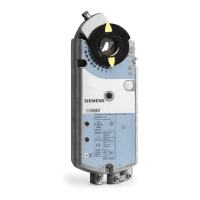
The Siemens OpenAir™ GLB..1E series comprises air damper actuators designed for open-close, three-position, and modulating control in ventilation and air conditioning plants. These electronic motor-driven actuators are suitable for regulating and shutting off air dampers, with a guideline for damper areas up to 1.6 m² (always observe the damper manufacturer's data). They are compatible with modulating controllers (DC 0/2...10 V), as well as open-close or three-position controllers for air dampers or air throttles. For rotary actuators operated with 3-point control, a minimum pulse length of 500 ms is recommended to ensure continuous and accurate operation.

Function Description

The GLB..1E actuators offer various control types depending on the specific model. The GLB141.1E, GLB142.1E, GLB146.1E, GLB341.1E, and GLB346.1E models support open-close and three-position control. The GLB161.1E, GLB163.1E, GLB164.1E, GLB166.1E, and GLB361.1E models are designed for modulating control (0/2...10 V).

The rotary direction can be clockwise or counter-clockwise, depending on the control type and the setting of the rotary direction switch (for open-close/three-position models) or the positioning signal (for modulating models). In the event of power loss or if the control signal is maintained at a constant value, the actuator remains in its achieved position.

Position indication is provided both mechanically and electrically. Mechanical indication is achieved using a position indicator. Electrical indication is available through a feedback potentiometer (for GLB142.1E) or an output voltage (U = DC 0...10 V) proportional to the rotary angle (for GLB16..1E and GLB361.1E), with the output voltage depending on the DIL switch setting for rotary direction.

Auxiliary switches (available on GLB146.1E, GLB166.1E, GLB346.1E) have switching points that can be set independently of each other in increments of 5° within 0° to 90°.

The self-adaptation of the linear span feature, when active, allows the actuator to automatically determine the mechanical end positions of the linear span and map the characteristic function (Uo, AU) to the calculated linear span.

Manual adjustment of the actuator is possible by pressing the gear train disengagement button. The rotary angle of the shaft adapter can also be mechanically limited with a set screw.

The actuators are driven by brushless, robust DC motors, ensuring reliable operation regardless of load. These motors do not require an end position switch, are overload-proof, and remain in place upon reaching the end stop. The gears are maintenance-free and low-noise.

Important Technical Specifications

  • Nominal Torque: 10 Nm (applies to all GLB..1E actuators)
  • Maximum Torque (blocked): 16 Nm
  • Minimum Holding Torque: 10 Nm
  • Nominal Rotary Angle (with position indication): 90°
  • Maximum Rotary Angle (mechanical limitation): 95° ± 2°
  • Runtime for 90° Rotary Angle: 150 s
  • Actuator Sound Power Level: 28 dB(A)

Power Supply:

  • GLB1..1E (SELV/PELV):
    • Operating voltage: AC 24 V ~ ±20% (19.2...28.8 V ~) / 50/60 Hz; DC 24...48 V = ±20% (19.2...57.6 V =) (C-UL: Permitted only to DC 30 V =)
    • Power consumption running: GLB14..1E: 2.2 VA / 1.3 W; GLB16..1E: 2.5 VA / 1.5 W
    • Power consumption holding: GLB14..1E: 0.5 W; GLB16..1E: 0.7 W
  • GLB3..1E:
    • Operating voltage: AC 100...240 V ~ ±10% (90...264 V ~) / 50/60 Hz
    • Power consumption running: GLB34..1E: 6 VA / 2 W; GLB36..1E: 4 VA / 1.5 W
    • Power consumption holding: GLB34..1E: 0.9 W; GLB36..1E: 0.6 W

Inputs (Positioning Signal):

  • GLB14..1E (AC/DC 24 V ~ / DC 24...48 V =): Wires 1-6/G-Y1 (clockwise), 1-7/G-Y2 (counterclockwise)
  • GLB34..1E (AC 100...240 V ~): Wires 4-6/N-Y1 (clockwise), 4-7/N-Y2 (counterclockwise)
  • GLB16..1E (DC 0/2...10 V =): Wires 8-2/Y-G0
    • Current consumption: 0.1 mA
    • Input resistance: >100 kΩ
    • Max. permissible input voltage: DC 35 V = (limited to DC 10 V =); max. AC 24 V ~ / DC 24...48 V =
  • Hysteresis: 60 mV (non-adjustable characteristic function), 0.6% of AU (adjustable characteristic function)
  • Adjustable Characteristic Function (GLB163.1E, GLB164.1E):
    • Offset Uo: DC 0...5 V =
    • Span AU: DC 2...30 V =
    • Max. input voltage: DC 35 V =; max. AC 24 V ~ / DC 24...48 V =

Outputs:

  • Position Indicator Output Signal (GLB16..1E, GLB36..1E): Wires 9-2/U-G0 (GLB16..1E), 9-2/U-G- (GLB36..1E)
    • Output voltage U: DC 0...10 V =
    • Max. output current: DC ±1 mA
    • Protected against faulty wiring: max. AC 24 V ~ / DC 24...48 V =
  • Aux. Power Supply (G-/G+) GLB36..: DC 24 V = ±20%, max. 10 mA
  • Feedback Potentiometer (GLB142.1E):
    • Change of resistance: 0...5000 Ω
    • Load: <0.25 W
    • Max. sliding contact current: <10 mA
    • Permissible voltage at potentiometer (SELV/PELV): AC 24 V ~ / DC 24...48 V =
    • Insulation resistance between potentiometer and housing: AC 500 V ~

Auxiliary Switches (GLB146.1E, GLB166.1E, GLB346.1E):

  • Switching voltage: AC 24...250 V ~ / DC 12...30 V =
  • Contact rating: 6 A resistive, 2 A inductive, min. 10 mA @ AC; 4 A resistive, 2 A inductive, min. 10 mA @ DC 30 V =; 0.8 A res., 0.5 A inductive, min. 10 mA @ DC 60 V =
  • Electric strength auxiliary switch against housing: AC 4 kV
  • Switching range: 5°...90° / 5°
  • Factory switch setting: Switch A: 5°; Switch B: 85°

Connection Cables:

  • Cable length: 0.9 m
  • Cross section of prewired connection cables: 0.75 mm²
  • Permissible length for signal lines: 300 m

Degree of Protection:

  • Insulation class (as per EN 60730): III (AC 24 V ~ / DC 24...48 V =, feedback potentiometer), II (AC 100...240 V ~, auxiliary switches)
  • Housing protection (as per EN 60529): IP 54

Environmental Conditions:

  • Operation: IEC 60721-3-3 Class 3K5, interior, weather-protected, -32...+55 °C, <95% r.F.
  • Transport: IEC 60721-3-2 Class 2K3, -32...+70 °C, <95% r.F.
  • Storage: IEC 60721-3-1 Class 1K3, -32...+50 °C, <95% r.F.
  • Mechanical Conditions: Class 2M2

Dimensions:

  • Actuator W x H x D: See "Dimensions" diagram on page 9.
  • Damper shaft: Round (8...16 mm), Round (8...10 mm with centering element), Square (6...12.8 mm)
  • Min. shaft length: 20 mm
  • Shaft hardness: <300 HV

Weight:

  • Without packaging: Max. 0.49 kg (without switches), Max. 0.63 kg (with switches)

Usage Features

The GLB..1E actuators are pre-wired with 0.9 m long connection cables, simplifying installation. The housing is made of flame retardant, non-brominated, non-chlorinated glass fiber reinforced plastic, ensuring durability and safety. The actuators are designed for easy integration into existing systems, with clear connection diagrams provided for various control types (open-close single wire, open-close two wire, three-position, and modulating control). The adjustable offset and span for the positioning signal on type-specific variations allow for fine-tuning to specific application requirements.

Maintenance Features

The GLB..1E actuators are maintenance-free, reducing the need for regular servicing and associated costs. The robust design, including brushless DC motors and maintenance-free gears, contributes to their long-term reliability. Potentiometers and auxiliary switches cannot be added in the field, which streamlines the product offering and ensures consistent performance. For disposal, the device is considered an electronics device in terms of European Directive 2012/19/EU and must be disposed of through designated channels, complying with all local and currently applicable laws and regulations.

Siemens OpenAir GLB 1E Series Specifications

General IconGeneral
BrandSiemens
ModelOpenAir GLB 1E Series
CategoryController
LanguageEnglish

Related product manuals