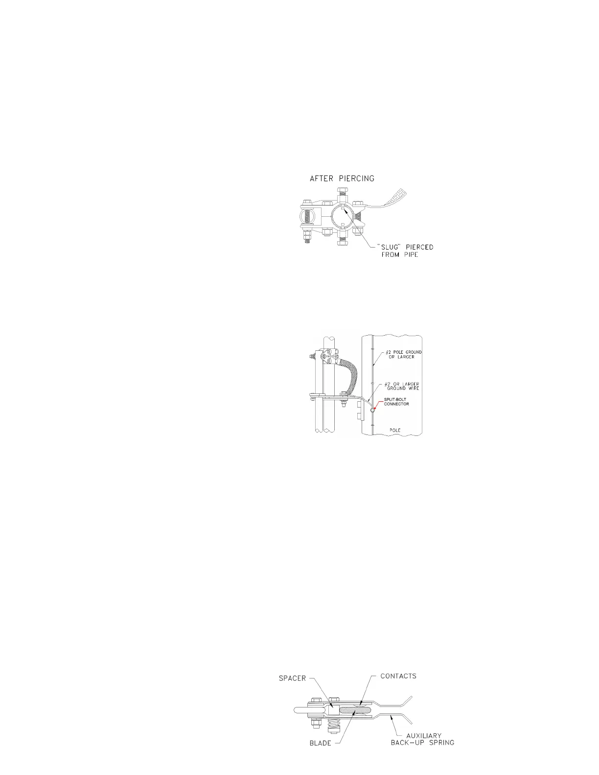
6. After the handle casting is in the final, properly adjusted position, make sure the four (4)
clamp bolts are fully tightened by tightening until the split washer is flattened. Then
tighten both piercing set screws until each set screw pierces through the wall of the
pipe.
NOTE: When tightening these set screws, the resistance will keep increasing and
then drop off sharply when the pipe is pierced. Fully tighten the set screws until
the shoulder of the set screw is firmly seated against the pipe.
7. The set screws help to ensure that when the switch handle is thrown open or closed,
the vertical pipe will definitely rotate along with the handle.
8. Ground the lock segment/handle assembly to the pole ground using a #2 or larger copper
wire (see below).
D. Operational check out instructions
1. SWITCHES ARE FULLY ADJUSTED AND INSPECTED, before they leave the factory. There
should not be any need to adjust the switch unit.
2. Check the rotation of the hinge terminals. They should rotate approximately 180° with
slight resistance.
3. When using hot stick removable interrupters insert the interrupters into the sockets and
turn clockwise to lock in place.
4. The following checks should be performed on all three phases, independently, to verify
proper operation of the switch and interrupters. This will be done manually.
a. Close the switch fully and lock the operating handle into the close position of the
lock segment. Bounce the blade toward the open position. The blade should stay
tight up against the spacer. If the blade does not stay up against the spacer readjust
the handle/lock segment assembly per Section C (above).
Phase-over-phase Vector® group-operated switches (600 and 900 A) Instruction Manual
8