EasyManua.ls Logo

Siemens QP Series - User Manual

Siemens QP Series
3 pages
Print Icon
To Next Page IconTo Next Page
Loading...
Siemens Building Technologies, Inc.
QP Series
Technical Instructions
Document No. 155-292
November 11, 2002
Pressure Switches for Gas and Air
GAS0047R1
mbar
LG
Description
QP… pressure switches are used for gas and air pressure supervision on industrial and
commercial burner applications.
The QPL31… series pressure switches break the electrical circuit when the pressure
drops below the adjusted value.
The QPH31… series pressure switches break the electrical circuit when the pressure
increases above the adjusted value.
Features
UL listed for USA and Canada, FM approved, ISO 9001 certified;
European approved versions available.
Adjustable pressure range from 1 to 112 inches water column (WC).
Automatic and manual reset models.
Surge protected up to 15 psi.
Product Numbers Table 1.
Pressure Range
Product Number Inches Water
Column (WC)
mbar Execution
QPL31.050M00 1 to 20 2.5 to 50
QPL31.140M00 7 to 55 17.5 to 137
Manual Reset Low
QPH31.050M00 2 to 20 5 to 50
QPH31.150M00 10 to 60 25 to 150
Manual Reset High
QPL31.050A00 1 to 20 2.5 to 50
QPL31.075A00 5 to 30 12.5 to 75
QPL31.280A00 28 to 112 70 to 280
Automatic Reset Low
QPH31.050A00 2 to 20 5 to 50
QPH31.090A00 5 to 35 12.5 to 87
QPH31.280A00 28 to 112 70 to 280
Automatic Reset High
Question and Answer IconNeed help?

Do you have a question about the Siemens QP Series and is the answer not in the manual?

Summary

QP Series Pressure Switches

Description

QP... pressure switches are used for gas and air pressure supervision on industrial and commercial burner applications.

Features

UL listed for USA and Canada, FM approved, ISO 9001 certified; European approved versions available.

Product Numbers

Lists product numbers with corresponding pressure ranges in inches water column and mbar, and execution type.

Specifications

Electrical Rating

Specifies the electrical rating for the switches as 10A @ 125 to 250 Vac and 1/3 HP @ 125 to 250 Vac.

Maximum Operating Pressure

Defines the maximum operating pressure for the QP series switches as 6 psi (400 mbar).

Operating Temperature

Specifies the operating temperature range for the switches from -40°F to 140°F (-40°C to 60°C).

Operation

Range Adjustment

Instructions on how to adjust the pressure cut-off setting using the range dial.

Manual Reset Models

Details on the manual reset procedure for switches with a yellow ring on the reset button.

Mounting and Wiring

Mounting Options

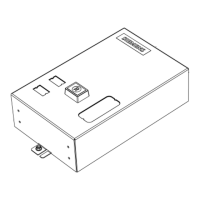
Switches can be mounted horizontally or vertically; feature a 1/4-inch NPT female pressure connection.

Wiring Requirements

Wiring must be performed by a licensed electrician; illustrates typical wiring for low and high pressure models.

Overview

The Siemens QP Series Pressure Switches are designed for the supervision of gas and air pressure in industrial and commercial burner applications. These devices are crucial for ensuring the safe and efficient operation of burner systems by monitoring pressure levels and triggering electrical circuit changes when predefined thresholds are met.

Function Description

The QP Series comprises two main types of pressure switches: the QPL31 series and the QPH31 series.

The QPL31 series are "low pressure" switches. These devices are configured to break the electrical circuit when the pressure drops below a user-adjusted value. This functionality is vital for applications where a minimum pressure must be maintained for safe operation. For instance, if a gas supply pressure falls too low, the QPL31 switch will open the circuit, shutting down the burner to prevent potential hazards such as flame instability or incomplete combustion. The QPL31 series includes both manual reset and automatic reset models. Manual reset models require an operator to physically reset the switch after a low-pressure event, ensuring that the cause of the pressure drop is investigated before restarting the system. Automatic reset models, on the other hand, will automatically re-engage the circuit once the pressure returns to an acceptable level, which can be useful in applications where brief, transient pressure fluctuations are common and do not pose a significant safety risk.

The QPH31 series are "high pressure" switches. These devices are designed to break the electrical circuit when the pressure increases above a user-adjusted value. This is essential for preventing over-pressure conditions that could damage equipment, lead to leaks, or create dangerous situations. For example, in a system where excessive air pressure could lead to an improper fuel-to-air mixture, a QPH31 switch would interrupt the circuit, stopping the burner until the pressure is brought back within safe limits. Similar to the QPL31 series, the QPH31 series also offers both manual reset and automatic reset models, providing flexibility based on the specific safety and operational requirements of the application.

Usage Features

The QP Series Pressure Switches are designed with several features to facilitate their use and integration into various systems:

  • Adjustable Pressure Range: The switches offer a wide adjustable pressure range, from 1 to 112 inches water column (WC), which corresponds to 2.5 to 280 mbar. This broad range allows them to be used in a diverse set of applications with varying pressure requirements. The adjustment is made by removing the cover and turning a range dial. Turning the dial clockwise increases the pressure setting, while turning it counterclockwise decreases it. This straightforward adjustment mechanism simplifies commissioning and recalibration.
  • Mounting Flexibility: All QP Series switches can be mounted in either a horizontal or vertical position. This flexibility in mounting orientation allows for easier installation in different system layouts and confined spaces, optimizing the use of available room.
  • Standard Pressure Connection: All models are equipped with a 1/4-inch NPT female pressure connection on the metal base. This standard connection size ensures compatibility with common piping and tubing systems, simplifying installation and reducing the need for specialized adapters.
  • Manual Reset Indication: For manual reset models, a yellow ring on the reset button provides a clear visual indication when the switch is in the open position. If the yellow ring is visible above the cover, it signifies that the switch has tripped due to a pressure event and requires manual intervention to reset, ensuring that operators are aware of the system status before attempting to restart the burner.
  • Surge Protection: The devices are designed with surge protection up to 15 psi (1 bar) for 2 seconds. This feature enhances the durability and reliability of the switches by protecting them from transient pressure spikes that might otherwise cause damage or false trips.
  • Electrical Wiring: The switches feature clear electrical terminals (COM, NO, NC) for straightforward wiring. Wiring must be performed by a licensed electrician to ensure safety and proper functionality. The wiring diagrams provided illustrate typical connections for both low and high-pressure models, showing how the common (COM), normally open (NO), and normally closed (NC) contacts are used to control the burner circuit.

Maintenance Features

While the manual does not explicitly detail maintenance procedures, several aspects of the QP Series design contribute to ease of maintenance and long-term reliability:

  • Robust Construction: The switches are built to withstand the rigors of industrial and commercial environments, contributing to a longer service life and reduced need for frequent replacement.
  • Leakage Check Requirement: After installation, it is recommended to check all connections for leakage. This is a critical step to ensure the integrity of the pressure system and prevent potential hazards, especially when dealing with gas.
  • Certifications: The QP Series switches are UL listed for USA and Canada, FM approved, and ISO 9001 certified. These certifications attest to the quality, safety, and reliability of the devices, indicating that they meet stringent industry standards. This provides assurance that the components are designed and manufactured to a high standard, which typically translates to fewer failures and less maintenance over time.
  • Clear Adjustment Mechanism: The simple and accessible range adjustment mechanism means that recalibration or setting changes can be performed quickly and accurately, minimizing downtime during system tuning or troubleshooting.
  • Visual Reset Indicator: For manual reset models, the yellow ring on the reset button serves as an immediate visual cue for maintenance personnel, allowing for quick identification of a tripped switch without extensive diagnostic work. This helps in efficient troubleshooting and reduces the time required to bring a system back online after a pressure event.

Siemens QP Series Specifications

General IconGeneral
TypeCircuit Breaker
Interrupting Rating10kA
SeriesQP
Poles1 or 2
StandardsUL Listed

Related product manuals