Technical Instructions QP Series Pressure Switches for Gas and Air
Document Number 155-292
November 11, 2002
Information in this publication is based on current specifications. The company reserves the right to make changes in specifications and models as
design improvements are introduced. Other product or company names mentioned herein may be the trademarks of their respective owners.
© 2002 Siemens Building Technologies, Inc.
U.S.A.
Document No. 155-292
Printed in the U.S.A.
Page 2
Specifications
Electrical rating
Maximum operating pressure
Maximum surge pressure
Operating temperature
10A @ 125 to 250 Vac
1/3 HP @ 125 to 250 Vac
6 psi (400 mbar)
15 psi (1 bar) for 2 seconds
–40°F to 140°F (–40°C to 60°C)
Operation
Range Adjustment
Remove the cover to adjust the pressure cut-off setting. Turn the range dial clockwise to
increase the pressure setting, or counterclockwise to decrease the pressure setting.
Manual reset models
If the yellow ring of the reset button is above the cover, the switch is in the open position
and must be manually reset before continuing burner operation.
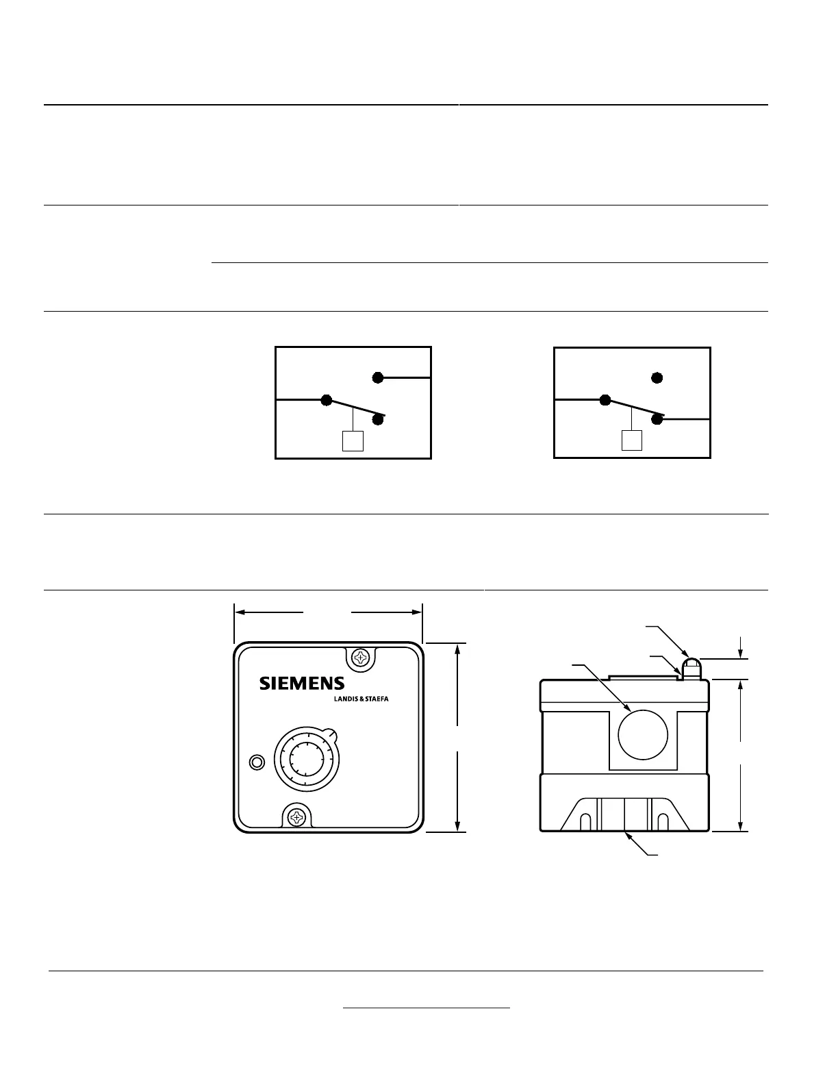
Wiring
NOTE: Wiring must be performed by a licensed electrician.
COM
NC
NO
P
LOW
PRESSURE
MODEL
GAS0043R1
Figure 1. Typical Wiring for Low
Pressure Models.
COM
NC
NO
P
HIGH
PRESSURE
MODEL
GAS0044R1
Figure 2. Typical Wiring for High
Pressure Models.
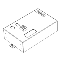
Mounting
• All switches can be mounted in either a horizontal or vertical position.
• All models have a 1/4-inch NPT female pressure connection on the metal base.
• Check connections for leakage after installation.
Dimensions
10
25
2
3
20
50
5
13
15
37
mbar
LG
INCH
W.C.
3.00"
(76.2 mm)
3.00"
(76.2 mm)
GAS0046R1
2.67"
(67.8 mm)
1/4" N.P.T. (Female)
Gas Inlet
Yellow
Ring
∅.88" (22.22 mm)
(1/2" Connection)
(Manual Reset
Models Only)
Reset Button
.40"
(10.16 mm)
GAS0045R1

 Loading...