Do you have a question about the Siemens SCALANCE X-200 and is the answer not in the manual?
Provides essential safety notices for setting up, operating, and maintaining the device.
Covers warnings regarding voltage, opening the device, and use in hazardous areas.
Details explosion hazards and requirements for use in hazardous environments.
Provides specific requirements for hazardous areas as per ATEX directives.
Specifies precautions for using cables in high-temperature environments.
Advises on preventing transient overvoltages and ensuring SELV supplies.
Details various options to increase network availability with optical or electrical topologies.
Describes the structure and function of media redundancy in ring topologies.
Conforms to MRP standard, specifies reconfiguration time, and lists requirements.
Specifies MRPD procedure for PROFINET IRT redundancy with path duplication.
Describes HSR method for ring topologies, including reconfiguration time and requirements.
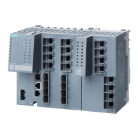
Provides a comparative overview of product characteristics across different SCALANCE models.
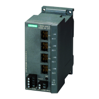
Describes product characteristics and possible attachments for SCALANCE XF204.
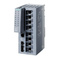
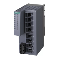
Describes product characteristics and possible attachments for SCALANCE X208.
Describes product characteristics and possible attachments for SCALANCE XF208.
Describes product characteristics and possible attachments for SCALANCE X216.
Describes product characteristics and possible attachments for SCALANCE X224.
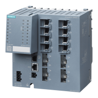
Details product features and possible attachments for X204-2 and X204-2TS.
Describes product characteristics and possible attachments for SCALANCE XF204-2.
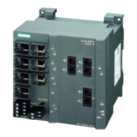
Describes product characteristics and possible attachments for SCALANCE X206-1.
Details the meaning and status indications of various LEDs on the device.
Explains the meaning of the red LED indicating device problems or specific events.
Details the status indications of the two-color LEDs for network interfaces.
Explains the green LED indicating redundancy manager status (active, standby, disabled).
Describes the yellow LED indications for standby function status (enabled, lost, disabled).
Lists various installation methods like DIN rail, S7 rail, and wall mounting.
Provides instructions for installing the IE Switch X-200 on a 35 mm DIN rail.
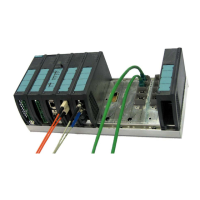
Details the procedure for installing the IE Switch X-200 on an S7-300 standard rail.
Explains how to perform wall mounting, including required fittings and notes.
Explains power connection methods using terminal blocks and specific connectors for IRT PRO models.
Details the signaling contact connection, its function, and exceptions for IRT PRO models.
Describes grounding methods for DIN rail, S7 rail, and wall mounting installations.
Details methods for assigning an IP address: DHCP, STEP 7, and Primary Setup Tool.
Guides on downloading, installing, and working with the Primary Setup Tool.
Covers language selection, network adapter selection, and network browsing.
Describes how to configure module IP address, subnet mask, and router settings.
Provides steps to transfer configuration data from PST to the device.
Guides on starting WBM, logging in with user credentials, and security notes.
Explains the WBM navigation bar (Console, Support, Log out) and buttons (Refresh, Set Values).
Covers starting CLI via Windows console or WBM, and using command shortcuts.
Explains how to configure system parameters like PNIO Device Name, System Contact, and Location.
Allows changing passwords for Admin and User accounts, with default passwords noted.
Allows monitoring link status and redundant power supply, with options for enabling monitoring.
Configures ports for fast ring redundancy and selects the required redundancy method (MRP, HSR).
Enables standby manager for redundant coupling of HSR rings and configures standby partners.
Options for IP address assignment (dynamic/fixed) and enabling access protocols like TELNET and SSH.
Configures how the switch reacts to system events like link changes or power status.
Configures sending email notifications for alarm events to a recipient.
Enables/disables port mirroring, monitors ports, and configures passive listening.
Displays current port status, type, mode, negotiation, link status, and allows port configuration.
Performs fault diagnostics on individual Ethernet ports to localize cable issues.
Specifies ports for activating loop detection and configuring reactions to detected loops.
Explains configuration and diagnostics using SNMP, including supported MIBs and access methods.
Details using PROFINET IO for diagnostics, parameter assignment, and alarm generation.
Explains how to link GSDML files in STEP 7 to include X-200 switches in PROFINET IO.
Guides on transferring device names to IE Switch X-200 for PROFINET IO communication.
Explains how to configure alarms for redundant power supply and C-PLUG in HW Config.
Details how to configure MRP parameters like Domain, Role, and Ring ports in STEP 7.
Describes how to configure port-specific topology settings for monitoring.
Details connector types and quantities for TP, FO, power supply, and signaling contact.
Lists power supply, power loss, current consumption, and overcurrent protection details.




 Loading...