4
Installation
4.1 Installation
Types of installation
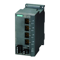
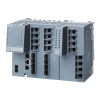
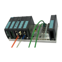
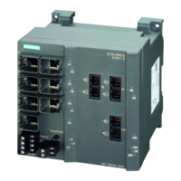
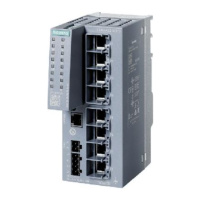
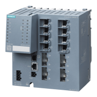
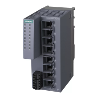
IE Switches X-200 can be installed in various ways:
● Installation on a 35 mm DIN rail
● Installation on a SIMATIC S7-300 standard rail (not possible with XF-200 IE switches)
● Wall mounting (not possible with the XF-200 IE switches)
WARNING
When used in shipbuilding, installation of SCALANCE X224, X216, X212-2, X212
-2LD,
X204IRT PRO, X202-2P IRT PRO and X201-3P IRT PRO on a 35 mm DIN rail is not
permitted.
In ships, the 35 mm DIN rail does not provide adequate support.
Note
Whe
n installing and operating the device, keep to the installation instructions and safety-
related notices as described here and in the manual SIMATIC NET Industrial Ethernet
Twisted Pair and Fiber Optic Networks /1/.
Unless stated otherwise, the mounting options listed below apply to all X-200 IE switches.
Note
Provi
de suitable shade to protect the IE Switch X-200 against direct sunlight. This avoids
unwanted warming of the IE Switch X-200 and prevents premature aging of the device
and cabling.
SCALANCE X-200
Operating Instructions, 12/2011, A5E00349864-19
129

 Loading...
