28
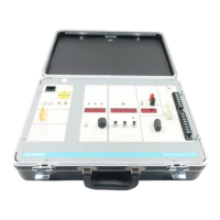
Testing Limitrip Devices
Settings of Bands and Pick-Ups
PICK-UP and BAND settings are made by closing or opening
switches grouped in DIP switch modules for the various
functions. A switch is closed when it is removed up, depress-
ing the end opposite the word open.
The PICK-UP or BAND setting is determined by the closed
switch, in each DIP switch module, FARTHEST AWAY from
the black highlighted number of letter. The setting of the
function controlled by a module is not affected by the position
(open or closed) of other switches in that module closer to the
black highlighted number or letter than the desired setting.
Where the black highlighted number is the largest number or
letter, the setting is controlled by the LOWEST closed switch
(LONG TIME PICK-UP, LONG TIME BAND, and SHORT
TIME PICKUP). Where the black highlighted number is the
smallest number, the setting is controlled by the HIGHEST
closed switch (INSTANTANEOUS PICK-UP and SHORT
TIME BAND). The device label adjacent to each switch
indicates the setting for that function if it is the farthest closed
switch. For example, if LONG TIME PICK-UP module switch
3 is the farthest closed switch from the black highlighted “F,”
the device is set at “C” setting of LONG TIME PICK-UP. If the
switches on a module are all open, the setting will be that
indicated by the black highlighted number.
Use peak responding “All Other Test,” for all Limitrip testing.
Test—Long Time Pick-Up
t is not necessary to operate the circuit breaker during the trip
device tests, the breaker can be left open.
1. Make all connections as described in the preceding
section, CONNECTIONS.
2. Set LONG TIME PICK-UP on “A” by closing (depressing)
the numbered end of the LONG TIME PICK-UP switch
labeled A in the Limitrip. Place the trip device test set
selector switch to STATIC TRIP TEST position. Set the
range switch on LOW. Set the POWER selector switch
to INTERNAL.
3. Turn the test set ON. The red digits of the meters should
come ON, (the alarm light may turn ON also, press the
STOP—alarm reset button). Press and hold the START
and RESET push buttons.
4. Slowly increase the current by rotating the INTERNAL
POWER CONTROL in a clockwise direction. Increase
the current until the LONG TIME PICK-UP light comes
ON; this should be at 0.5 ampere + 10%. The sampling
rate of the digital ammeter is such that the control must
be moved very slowly to accurately determine the pick-
up current of the trip device.
5. Decreasing the current slightly should cause the light to
go OUT.
6. Repeat the tests for the other phases and settings and
compare with Table 4.
Table 4
Limitrip Rating Table--Amperes
BreakerType
and Frame Size
Tripping XFMR
Rating (Primary)
Long Time Element Calibrated Pick-Up Settings Max. Cont
Rating
A B C D E F
LA600 600
Amperes
80 40 50 160 70 80 90 90
200 100 125 150 175 200 225 225
400 200 250 300 350 400 450 450
600 300 375 450 525 600 675* 600
LA1600 1600
Amperes
200 100 125 150 175 200 225 225
400 200 250 300 350 400 450 450
800 400 500 600 700 800 900 900
1600 800 11000 1200 11400 1600 1800* 1600
LA3000 3000
Amperes
2000 1000 1250 1500 1750 2000 2250 2250
3000 1600 2000 2400 2800 3200 3600* 3000
LA4000 4000
Amperes
4000 2000 2500 3000 3500 4000 4500* 4000
*Do not exceed the maximum continuous current rating of the circuit breaker.
 Loading...