Description
5
device under test trips or when the STOP push button is
operated.
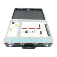
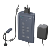
18. Reset Switch. This switch resets the relay circuit and the
stop clock. It also changes the time constant for the peak
responding ammeter allowing the ammeter to return to
zero in a shorter time.
19. Phase Selector Switch. Selects phase of device to be
tested .
20. Output Connector. This is a 15 pin connector that
accepts the cord sets: three cord sets are provided with
the test set. One cord set (18-732-184-506) provides
the means of connecting to STATIC TRIP II type trip
devices with the same color coded plugs as used in the
previous (PTS-3) test set. With the addition of alligator
clips this cord set is also used to test the first generation
trip devices. A second cord set (18-732-184-507) is
provided to connect to LIMITRIP style trip devices. This
cord set has coordinated color coding for the connec-
tions. A third cord set (18-732-184-508) is used to
connect to STATIC TRIP III devices.
21. Pick-Up Connection. This is a four pin connector to the
LED PICK-UP indicators for STATIC TRIP II and LIMITRIP.
22. DVM Actuator Test Output Terminals. These terminals,
mentioned earlier, are the input of the digital voltmeter
and when connected to the internal power supply by the
STATIC TRIP TEST/ACTUATOR TEST switch, become
the output to test the magnetic actuator of the circuit
breaker. When used as the actuator source, the positive
output is the red terminal and the negative is the black
terminal. When used as the voltmeter input, the meter
will read the same for either polarity.