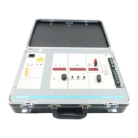
Testing Static Trip III Devices
7
POWER CONTROL in a clockwise direction. This is a five turn
control arranged for 50 Hz operation so a noticeable deadband
is evident at zero output and 60 Hz. Increase the current until
the LONG TIME pick-up light comes ON. This should be at
.275 ampere + 10%. The sampling rate of the ammeter is
such that the control must be moved very slowly to accurately
determine the pick-up current of the trip device. The pick-up
is always 110% of long time setting.
5. Decreasing the current should cause the light to go out.
6. Repeat the tests for the other phases and settings and
compare with Table 1.
Table 1
Long Time Element Calibrated Current Settings Ground Element Calibrated Pickup Settings
Sensor
Rating
(Pri-Amps)
.5 .55 .6 .65 .7 .75 .8 .85 .9 .95 1.0 Sensor
Rating
Primary
Amps
20% 30% 40% 50% 60%
150 75 82.5 90 97.5 105 112.5 120 127.5 135 142.5 150 150 30 45 60 75 90
200 100 110 120 130 140 150 160 170 180 190 200 200 40 60 80 100 120
300 150 165 180 195 210 225 240 255 270 285 150 300 60 90 120 150 180
400 200 220 240 260 280 300 320 340 360 380 400 400 80 120 160 200 240
600 300 330 360 390 420 450 480 510 540 570 600 600 120 180 240 300 360
800 400 440 480 520 560 600 640 680 720 760 800 800 160 240 320 400 480
1200 600 660 720 780 840 900 960 1020 1080 1140 1200 1200 240 360 480 600 720
1600 800 880 960 1040 1120 1200 1280 1360 1440 1520 1800 1600 320 480 640 800 960
2000 1000 1100 1200 1300 1400 1500 1600 1700 1800 1900 2000 2000 400 600 800 1000 1200
3200 1600 1760 1920 2080 2240 2400 2560 2720 2880 3040 3200 3200 400 600 800 1000 1200
4000 2000 2200 2400 2600 2800 3000 3200 3400 3600 3800 4000 4000 400 600 800 1000 1200
Secondary
Current
Amps
.25 .275 .30 .325 .35 .375 .40 .425 .45 .475 .50
Available Models
RMS-TI(T). Long Time and Instantaneous
RMS-TIG(T,Z) Long Time, Instantaneous and Ground Fault
RMS-TS(T,Z) Long Time and Short Time
RMS-TSG(T,Z) Long Time, Short Time and Ground Fault
RMS-TSI(T,Z) Long Time, Short Time and Instantaneous
RMS-TSIG(T,Z) Long Time, Short Time, Instantaneous and
Ground Fault Devices with (T,/Z) designation include
optional targets (T) and/or zone interlocking (Z).
General Notes
1. The “Tripping XFMR Rating” STATIC TRIP III represent
the primary current in amperes. The secondary rated
value is one half ampere.
2. The current settings of the long time element are switch
selectable and are calibrated at points .5 through 1.0 as
shown in the rating table. Pickup is 1.1 times the setting.
3. The pick-up setting of the short time delay element is
switch selectable and is calibrated at 2,3,4,5,6,7,8 and
12 multiples of the long time setting.
4. Instantaneous calibration at 2,4,6,8, 12 and 15 multiples
of tripping XFMR rating.
5. The pick-up settings of the ground elements are switch
selectable and are calibrated in multiples of the tripping
transformer rating as shown in the rating table.
6 The long time element has 5 bands which are field
selectable. The time delay at 6 multiples of pick-up is as
follows:
Band 1 —3.5 seconds Band 4—17 seconds
Band 2—6.0 seconds Band 5—30 seconds
Band 3—10 seconds
7. The ground element has 3 bands which are calibrated at
1, 25 and 4 seconds.
8. The short time element has 5 time bands
9. The maximum interrupting time is the maximum length
of time that fault current flows, including arcing time.
10. The lower limit of ground fault recognition is 25 amperes
for RL-800 breakers and 40 amperes for an RL-1600
breaker.