5/6
Siemens QAX30.1, QAX31.1 – Room units with PPS2 interface CA2N1741en_02
Building Technologies 2015-12-23
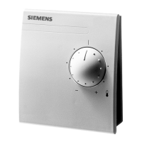
Connection terminals
The tool socket on the room unit provides access to the connected individual room
controller via the commissioning and service tool or the service terminal.
The bus cable (Terminals 3 and 4) is therefore looped to the tool socket (Pins 1 and 2).
The bus cable is not affected by the room unit.
For connection of a service terminal, the PPS2 interface (Terminals 1 and 2) is also
connected to the tool socket.
8 7 6 5 4 3 2 1
C–
C+
CP–
CP+
80085
PPS2 interface, supply voltage
CP+ 1 Device supply, Data PPS2 (pos.)
CP– 2 Device supply, Data PPS2 (neg.)
Bus connection (looped to tool socket)
C+ 3 With L
ONWORKS® bus (Desigo RXC): CLA
C– 4 With L
ONWORKS® bus (Desigo RXC): CLB
Standard type RJ45 tool socket.
With LONWORKS® bus (Desigo RXC): CLA
With L
ONWORKS® bus (Desigo RXC): CLB
Not used
Not used
Not used
Not used
CP+ Data PPS2
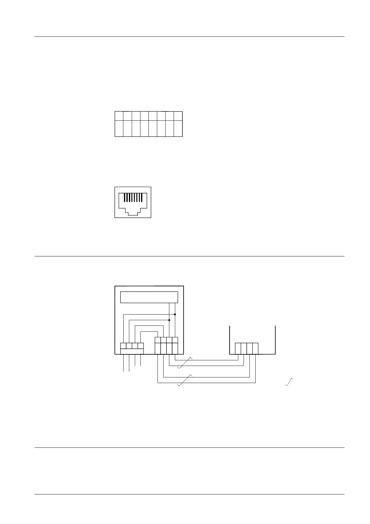
Connection diagram (Example: RXC)
The following example shows the room unit connected to a Desigo RXC room
controller:
1741A03
PPS2
Tool
A
R1
B
7 8 1
2
4 3 2
1
C–
C+
CP–
CP+
N1
CP+
CP–
CLA
CLB
PPS2
LonWorks® Bus
= Twisted pair
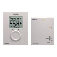
R1 Room unit QAX30.1
N1 Room controller RXC...
A Connection for RXT10 commissioning and service tool
B Connection for service terminal with PPS2 interface
Dimensions
 Loading...