EasyManua.ls Logo

Siemens 2000 Series User Manual

Siemens 2000 Series
3 pages
To Next Page IconTo Next Page
Page #1 background imageLoading...
Page #1 background image
Quick Reference Guide
Document No. 129-363
May 13, 2015
Series 2000 (Interactive) Room
Temperature Sensors, TEC, Standard
Design and Semi-Flush Mount
Item Number 129-363, Rev. DA Page 1 of 3
Overview
For high-end Terminal Equipment Controller (TEC)
applications, these sensors allow users to view and
adjust points in the controller using the sensor buttons
and digital display.
A user-programmable display allows the simultaneous
monitoring of the temperature, a user-selected point
and day/night operation status.
Features
User-programmable two-line liquid crystal
display
Simultaneous display of temperature, a user-
selected point, and day/night operation status
Backward compatibility with all TECs, including
PTECs.
Hardware-protected security
Standard RJ-11 terminated cable
No separate power source requirement
Digital (error-free) setpoint adjustment
Product Numbers
Description Product Number
Desert Beige
White
TEC Sensors
540-650A
540-650B
TEC Sensors with
Fan-Speed
Control (Momentary
contact)
540-652A
540-652B
TEC Semi-Flush
Mount
QAA1280FWSC
Accessories
Description Product Number
Passkey
544-643A
Computer cable
540-143
Applications
Operating rooms
Laboratories
Isolation rooms, with pressurization as the
critical point
Other difficult control spaces
Executive suites and other high-profile areas
Operation
Buttons
The function of each button varies, depending on the
current screen. For detailed instructions, see Operating
Instructions.
Operation modes
Figure 1. Operation Modes.
Question and Answer IconNeed help?

Do you have a question about the Siemens 2000 Series and is the answer not in the manual?

Siemens 2000 Series Specifications

General IconGeneral
Control ModePID, On/Off
Input TypeThermocouple, RTD
Output TypeRelay, Analog, SSR
Supply Voltage100-240 VAC
DisplayLED
CommunicationRS-485
Operating Temperature0-50°C

Summary

Overview of Series 2000 Sensors

Key Features of Series 2000 Sensors

Series 2000 Product Numbers

Applications for Series 2000 Sensors

Operation and Controls

Sensor Buttons

Details button functions vary based on the current screen.

Normal Operation Mode

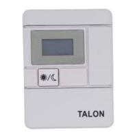
Describes sensor behavior when no passkey or laptop is connected.

Passkey Usage

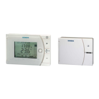
How to use the passkey to view/change controller points and set display options.

Laptop Connection Mode

Connecting a laptop for communication, which deactivates sensor buttons.

Important Considerations

Display Messages Explained

Technical Specifications

Operating Instructions

Setpoint Adjustment (Day Operation)

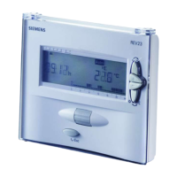
Step-by-step guide to view and change the setpoint during day operation.

Night Override Functionality

Procedure for selecting day operation using the override button.

Viewing Point Descriptions

Instructions for viewing detailed descriptions of controller points.

Viewing and Commanding Point Values

Guide to viewing point values and commanding changes.

Setting Display Options

Steps to configure display elements like temperature and critical point.

Releasing Points and Resetting Values

Procedure to release points from override or reset to factory defaults.

Related product manuals