EasyManua.ls Logo

Siemens REV24RF

Siemens REV24RF
18 pages
To Next Page IconTo Next Page
Loading...
CE1N2206en
24.04.2008
Building Technologies
s
2
206
REV24RF.. RCR10/868
Radio set with 7-day
room temperature
controller
REV24RF../SET
Comprising a room temperature controller (with integrated radio transmitter)
and receiver with relay outputs
Mains-independent, battery-operated room temperature controller featuring
user-friendly operation, easy-to-read display and large numbers.
Self-learning two-position controller with PID response (patented).
Operating mode selection:
- 7-day automatic mode with max. 3 heating or cooling phases.
- Continuous comfort mode.
- Continuous energy saving mode.
- Protection against frost or overheating.
- Exception day (24 hour operation) with max. 3 heating or cooling phases.
A separate temperature setpoint can be entered in automatic mode and for
the exception day for each heating or cooling phase.
Heating zone control.
Possibility to control cooling equipment.
Advantage for retrofitting, renovating, and reconstruction purposes
(completely wireless room unit).
Use
Room temperature control in:
Single-family and vacation homes.
Apartments and offices.
Individual rooms and professional office facilities.
Commercially used spaces.
Control for the following equipment:
Magnetic valves of an instantaneous water heater.
Question and Answer IconNeed help?

Do you have a question about the Siemens REV24RF and is the answer not in the manual?

Siemens REV24RF Specifications

General IconGeneral
Power Supply24 V AC/DC
DisplayLCD
Communication ProtocolRF
MountingWall mounted
Control ModeOn/Off
Output TypeRelay
CommunicationWireless
Housing MaterialPlastic
Protection ClassIP20
Switching Current5 A
Frequency50 Hz
Control AlgorithmPI

Summary

Radio Set Overview

Mechanical Design

Controller and Base Unit

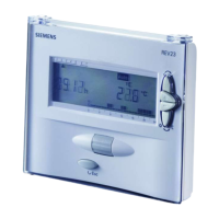
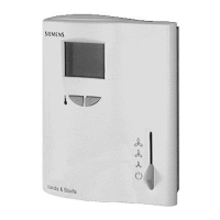
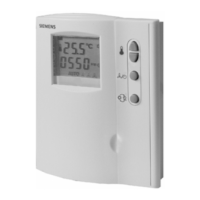
Describes the plastic casing, display, controls, and battery compartment of the room controller.

Table Stand

Details the base for wall mounting and the separate table stand for placement.

User Interface and Operation

Display Elements Explained

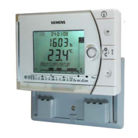
Explains the various icons, text lines, and symbols shown on the controller's display.

Operating Mode Selection

Details the available operating modes like Auto, Continuous Comfort, Energy Saving, and Protection.

Control Button Functions

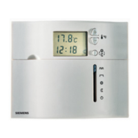
Describes the function of the INFO, Plus, Override/Party, and Minus buttons for operation.

Time Switch Programming

Automatic Weekly Schedules

Details how to program comfort phases and energy saving temperatures for automatic weekly schedules.

Continuous Operating Modes

Setpoint Configuration

Factory Default Setpoints

Lists the pre-configured temperature settings for heating and cooling modes.

Holiday and Absence Programming

Technical Features

DIP Switch Configuration

Explains the function and settings of each DIP switch for controller behavior.

Synchronization and Notes

Time Signal Synchronization

Details the automatic synchronization process with the time signal from Frankfurt.

Advanced Settings and Checks

Expert Level Access and Navigation

Describes the procedure to enter and navigate the engineering settings menu.

DIP Switch Reset and Functional Checks

Explains DIP switch reset and outlines steps for verifying controller operation.

Radio Reception Considerations

Discusses factors affecting radio signal reception and error indication.

System Reset Procedures

Resetting Controller and Receiver Data

Details options to reset controller data, faulty receiver data, or all receiver data.

Installation Guidance

Optimal Room Unit Placement

Provides advice on choosing the best location for the room unit for accurate temperature sensing.

Mounting and Installation

Controller Wall Mounting

Instructions for attaching the room unit to a wall, including clearance and interference considerations.

Receiver Unit Installation

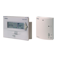
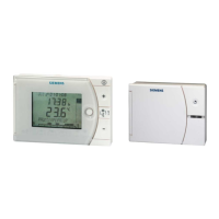
Guidelines for mounting and wiring the receiver unit, emphasizing safety during wiring.

Commissioning Procedures

Radio Link Testing and Optimization

Steps to test and optimize the radio communication quality between the controller and receiver.

Manual Operations and Notes

Manual Relay Override

How to manually activate or deactivate the receiver's relay output for testing.

Manual Controller-Receiver Pairing

Procedure for manually connecting the room controller to the receiver unit.

Operational Notes and Error Indicators

Explains error indicators and operational behavior for radio link issues.

Controller Technical Specifications

General Unit Data and Standards

Covers power, batteries, protection class, CE conformity, and applicable directives.

Environmental and Physical Specs

Details operating conditions, weight, color, and physical dimensions of the controller.

Receiver Technical Specifications

General Unit Data and Standards

Covers voltage, power, relay capacity, CE conformity, and directives for the receiver.

Environmental and Physical Specs

Details operating conditions, weight, color, and physical dimensions of the receiver.

Connection Diagrams

Application Wiring Examples

Shows how to wire the receiver to different heating and cooling appliances.

Product Dimensions

Related product manuals