EasyManua.ls Logo

Siemens RCC30 User Manual

Siemens RCC30
8 pages
To Next Page IconTo Next Page
Page #1 background imageLoading...
Page #1 background image
CE1N3023en
2017-11-14
Building Technologies
3
023
Room Temperature Controller
RCC30
for four-pipe fan coil units
Outputs for on / off valve actuators
Outputs for three-speed fan
Control depending on room or return air temperature
Operating modes: normal, energy saving and frost protection or OFF
Operating mode changeover input for remote control
Selectable control parameters
Operating voltage AC 230 V
Use
Typical use:
Control of the room temperature in individual rooms that are heated or cooled with
four-pipe fan coil units.
For opening or closing a valve
for switching a three-speed fan.
Functions
The controller acquires the room temperature with its integrated sensor or external
room temperature sensor (QAA32) or external return air temperature sensor (QAH11.1)
- if used - and maintains the setpoint by delivering control commands to the 2-point-
valve.
The switching differential is adjustable. It can be 1 or 4 K in heating mode and
0.5 or 2 K in cooling mode.
Question and Answer IconNeed help?

Do you have a question about the Siemens RCC30 and is the answer not in the manual?

Siemens RCC30 Specifications

General IconGeneral
Control ModePID, On/Off
MountingPanel Mount
Input TypeThermocouple, RTD
Output TypeRelay
Temperature RangeDepends on sensor type

Summary

Use and Functions

Typical Use Cases

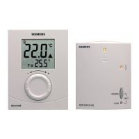
Control of room temperature in individual rooms with four-pipe fan coil units for valves and fans.

Core Functions

Controller acquires room temperature and maintains setpoint by controlling 2-point valves.

Operational Modes

Fan Operation Control

Fan is switched to selected speed or temperature-dependent control.

Heating Mode Operation

Details OPEN/CLOSE commands for the heating valve based on room temperature.

Cooling Mode Operation

Details OPEN/CLOSE commands for the cooling valve based on room temperature.

Return Air Temperature Control

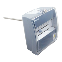
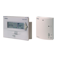
Control based on measured room or return air temperature for automatic changeover.

Operating Mode Settings

Normal Operation Mode

Heating or cooling with automatic changeover and manual fan speed.

Frost Protection Mode

Automatic activation below 8°C or manual via standby or switch.

Energy Saving Mode

Fixed setpoints (16°C heating, 28°C cooling) activated by input D1.

Mode Changeover Switch Input

Input D1 changes modes based on switch contact (open window, etc.).

Configuration and Design

Mechanical Design Overview

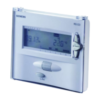
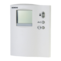
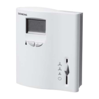
Unit consists of plastic housing with electronics and a mounting base.

Setting and Operating Elements

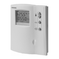
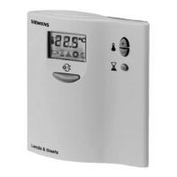
Details physical controls like mode selector, LEDs, and setpoint adjustment.

DIP Switch Functions

Explains the purpose of each DIP switch for fan control and mode settings.

Installation and Technical Data

Mounting and Installation Notes

Guidance on mounting location, wiring, and initial setup checks.

Technical Specifications

Details power supply, operational data, environmental conditions, and certifications.

Connections and Dimensions

Connection Terminals and Diagram

Illustrates terminal assignments and wiring for sensors, outputs, and power.

Unit and Baseplate Dimensions

Provides physical dimensions for the controller unit and its mounting baseplate.

Related product manuals