4/8
Siemens Room temperature controller CE1N3023en
Building Technologies 2017-11-14
Mechanical design
The unit consists of two parts:
∂ A plastic housing which accommodates the electronics, the operating elements and
the built-in room temperature sensor
∂ A mounting base
The housing engages in the mounting base and snaps on.
The base carries the screw terminals.
The DIP switches are located at the rear of the housing.
3021Z01
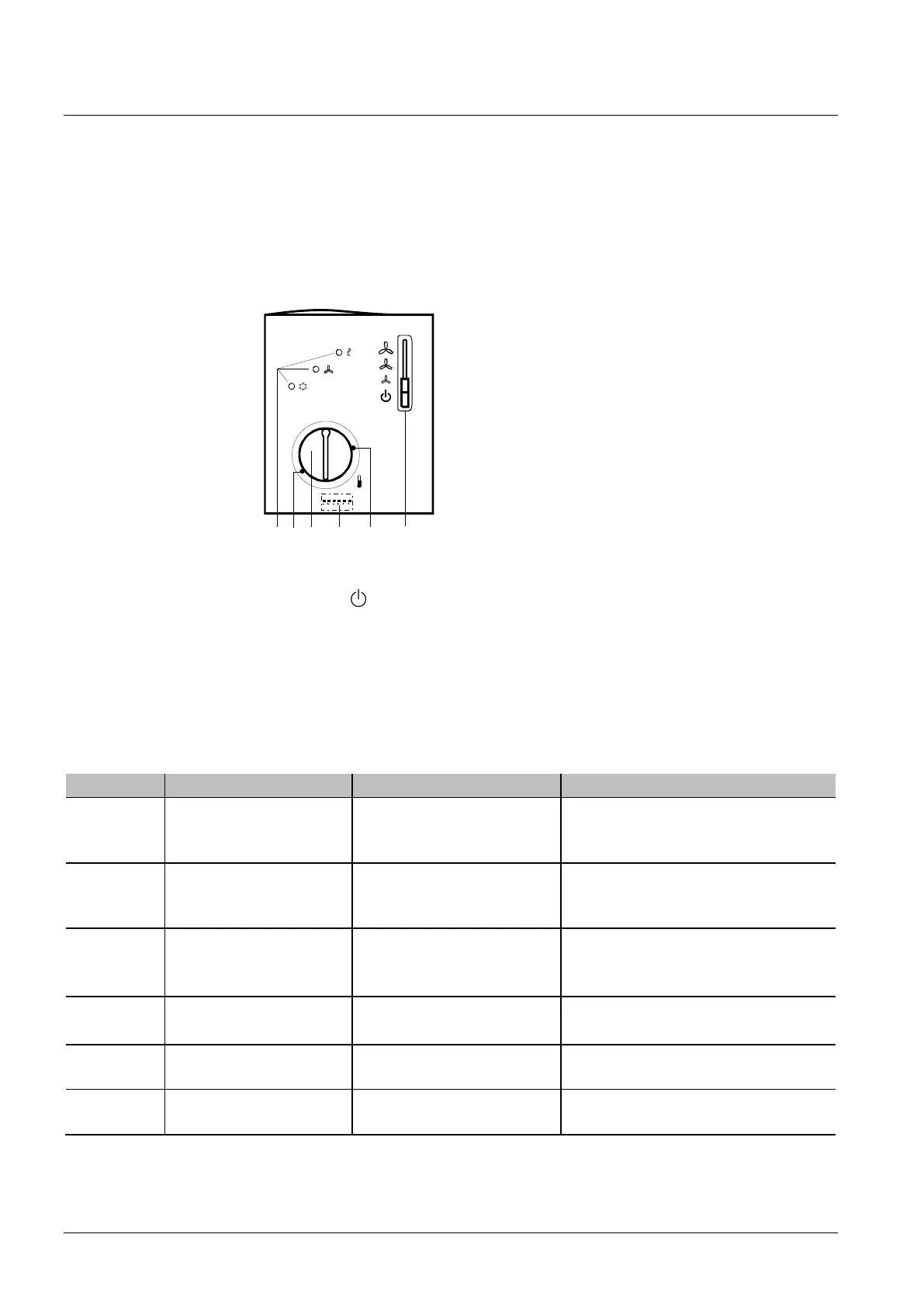
2 5 6 13 4
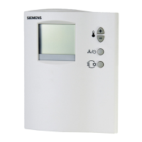
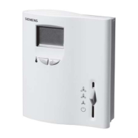
1. Operating mode selector
(standby , heating or cooling mode with manual selection of fan speed)
2. LEDs for indicating heating mode, cooling mode and fan operation
3. Setting facility for minimum setpoint limitation
(in increments of 1 K)
4. Setting facility for maximum setpoint limitation
(in increments of 1 K)
5. Room temperature setpoint knob
6. Set of DIP switches
DIP switch no. Meaning Position ON Position OFF
1 Fan control Fan control is temperature-
dependent in all operating
modes
Fan control in normal operation is tem-
perature- independent
1)
2 Operating mode change-
over via external switch
Changeover between normal
operation and energy saving
mode
Changeover between normal operation
and standby
1)
3 Operating action of switch
for external operating
mode changeover
Changeover activated when
contact of switch is closed
(N.O.)
1)
Changeover activated when contact of
switch is open
(N.C.)
4 Standby Frost protection function not
enabled
Frost protection function enabled
1)
5 Switching differential 1 K in heating mode
1)
0.5 K in cooling mode
1)
4 K in heating mode
2 K in cooling mode
6 Dead zone in
normal operation
2 K
1)
5 K
1) Factory setting
Setting and operating
elements
Legend

 Loading...