11 / 13
Siemens RDD100.1RFS Wireless room thermostat with LCD CB1N1424en
Building Technologies 2017-11-21
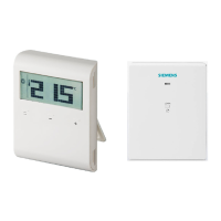
Connection diagrams
Q11
Q14
N2
L
N
Q12
AC 230 V
AC 24...230 V
Y1
8 (2) A
Max.
T
LL
N1
1424A01
10 A 10 A
L Live, AC 230 V
Q11 Live, AC 24…230 V
Q14 NO contact, AC
24…230 V/8(2) A
Q12 NC contact, AC
24…230 V/8(2) A
N Neutral conductor
Nx Neutral conductor
N1 Transmitter
RDD100.1RF
N2 Receiver RCR100RF
Y1 Actuating device
L – N AC 230 V/Lx – Nx AC 24…230 V
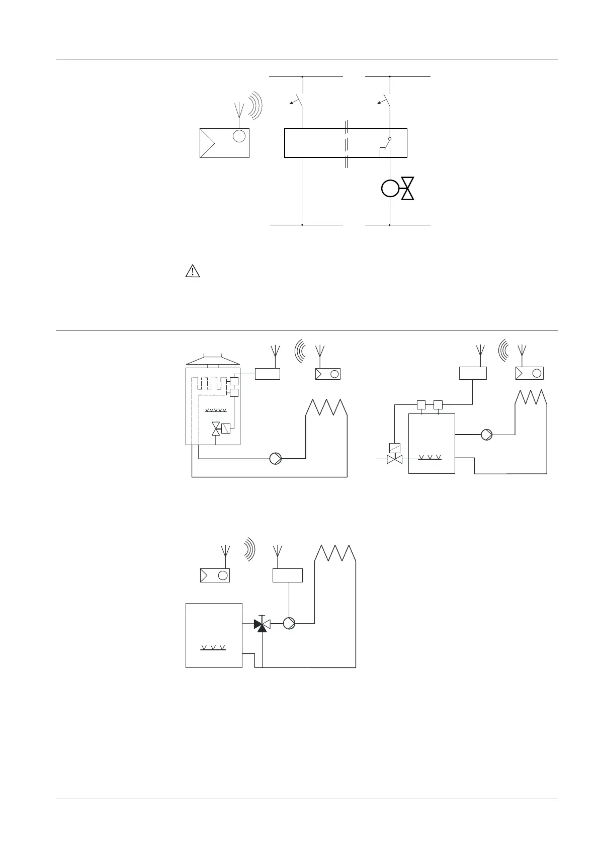
Application examples
T
T
F1
F2
N2
M1
Y2
N1
T
F1F2
N2
M1
Y2
T T
T
N1
Wireless room thermostat with receiver,
control of a gas-fired wall-hung boiler
Wireless room thermostat with receiver,
control of a gas-fired floor-standing
boiler
Y1
M1
N2
T
N1
F1 Thermal reset limit thermostat
F2 Safety limit thermostat
M1 Circulating pump
N1 RDD100.1RF room thermostat
N2 RCR100RF receiver
Y1 3-port valve with manual
adjustment
Y2 Magnetic valve
Wireless room thermostat with receiver,
control of a heating circuit pump
(precontrol by manual mixing valve)
 Loading...