23 / 46
Siemens RDF300… / RDF340... / RDF400… / RDF600… Basic Documentation CE1P3076.en
Smart Infrastructure 2020-02-21
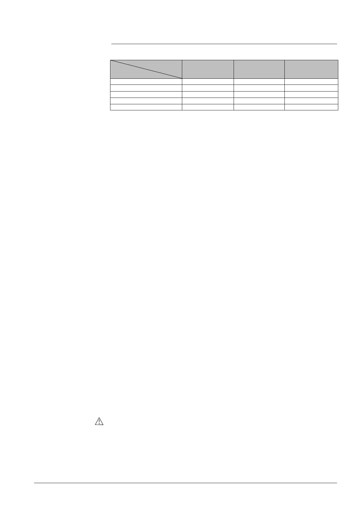
4.7 Control outputs
Different control output signals are available depending on the controller type.
Control output
Type reference
RDF300… Y11, Y21 (2) Y11/Y21 (1)
RDF400… Y11, Y21 (2) Y11/Y21 (1)
RDF340… Y10, Y20 (2)
RDF600 Y11, Y21 (2) Y11/Y21 (1)
RDF600T Y11, Y21 (2) Y11/Y21 (1)
( ) Number of outputs
The valve or compressor receives the OPEN/ON command via control output Y11
or Y21:
1. When the acquired room temperature is below the setpoint (heating mode) or
above the setpoint (cooling mode).
2. When control outputs Y11/Y21 were not energized for more than the “Minimum
output off time” (factory setting 1 minute, adjustable via parameter P48).
The valve or compressor receives the CLOSE/OFF command via control output
Y11 or Y21:
1. When the acquired room temperature is above the setpoint (heating mode) or
below the setpoint (cooling mode).
2. When control outputs Y11/Y21 were energized for more than the “Minimum
output on time”; (factory setting 1 minute, adjustable via parameter P49).
Output Y11 provides the OPEN command, and Y21 the CLOSE command to the 3-
position actuator. The factory setting for the runtime is 150 seconds (adjustable via
parameter P44 from 50…240 seconds).
1. When the controller gets powered up, a closing command for the actuator
runtime + 150% is provided to ensure that the actuator fully closes and
synchronizes to the control algorithm. (RDF3..., 4...: SW < 3.1: + 20%).
2. When the controller calculates the positions fully close or fully open, the
actuator runtime is extended + 150% to ensure the right actuator position
synchronized to the control algorithm. (RDF3..., 4...: SW < 3.1: + 20%).
3. After the actuator reaches the position calculated by the controller, a waiting
time of 30 seconds is applied to stabilize the outputs.
The electrical heater receives an ON command via the auxiliary heating control
output Y21:
1. When the acquired room temperature is below “setpoint for electrical heater”.
2. When the electrical heater has been switched off for more than 1 minute.
The OFF command for the electrical heater is output:
1. When the acquired room temperature is above the setpoint (electrical heater).
2. When the electrical heater has been switched on for more than 1 minute.
A safety thermostat (to prevent overheating) must be provided externally.
The demand calculated by PI control from the current room temperature and
setpoint is provided via Y10 and Y20 to the valve actuator as a continuous
DC 0...10 V signal.
Overview of control
on/off control signal
(2-position)
3-position control
Electrical heater
control signal
(2-position)
DC 0..10 V control
 Loading...