Do you have a question about the Siemens RDG110U and is the answer not in the manual?
Highlights core features and lists the different Siemens RDG thermostat models available.
Details compatibility of RDG thermostats with various fan coil unit system configurations.
Outlines the use of RDG thermostats with chilled/heated ceiling and radiator systems.
Specifies compatibility of RDG thermostats with heat pumps and DX-type equipment.
Covers temperature control, mode changeover, fan speed adjustment, and setpoint limits.
Details timer functions, remote control, and the use of digital and multifunctional inputs.
Illustrates wiring diagrams for 2-pipe fan coil unit applications with RDG thermostats.
Shows wiring for 2-pipe fan coil units with electric heaters using RDG thermostats.
Wiring diagrams for 2-pipe fan coil units with radiator/floor heating.
Wiring diagrams for 4-pipe fan coil unit applications with RDG thermostats.
Wiring diagrams for 4-pipe fan coil units with electric heaters using RDG thermostats.
Summarizes control outputs and fan capabilities for different RDG models.
Illustrates wiring diagrams for chilled/heated ceiling applications with RDG thermostats.
Wiring diagrams for 2-stage chilled/heated ceiling systems using RDG thermostats.
Wiring diagrams for chilled ceiling systems with radiator/floor heating.
Summarizes control outputs for RDG models used in chilled systems.
Wiring diagrams for systems with compressors for heating or cooling.
Wiring diagrams for systems with compressors and electric heaters.
Wiring diagrams for 2-stage compressor systems.
Summarizes control outputs and fan capabilities for compressor systems.
Table summarizing features like operating voltage, control outputs, and fan types for each RDG model.
Lists compatible actuators, sensors, and accessories for RDG thermostats.
Details compatibility for 3-position, DC 0-10V, and electrothermal actuators.
Provides maximum numbers of actuators that can be connected in parallel for different RDG models.
Details product numbers, stock numbers, and designation for ordering thermostats and kits.
Describes the physical construction of the room thermostat, including housing and mounting plate.
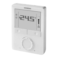
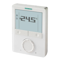
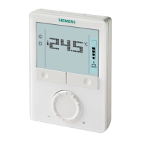
Illustrates the physical controls on the thermostat for operation and setting adjustments.
Explains the meaning of various icons displayed on the thermostat screen.
Details the symbols used for status, modes, and temperature readings on the display.
Provides guidelines on the optimal location and method for mounting the thermostat.
Highlights crucial safety warnings and precautions related to thermostat wiring.
Step-by-step guide for initial setup and commissioning of the thermostat.
Describes the temperature unit selection wizard and sensor calibration process.
Information on the proper disposal of the electronic device according to regulations.
Details voltage, power consumption, and output capabilities for RDG100/RDG110.
Describes the types, ranges, and functions of inputs for RDG100/RDG110.
Information regarding eco design and EU labelling directives applicable to RDG100.
Covers power supply, control outputs, and input specifications for the RDG110U model.
Details power supply, control outputs, and input specifications for the RDG160T model.
Covers operational data, switching differentials, and setpoint ranges for RDG160T.
Details environmental operating conditions, transport, storage, and applicable standards.
Diagrams showing terminal connections for RDG100, RDG100T, RDG100T/H, and RDG110.
Diagrams illustrating terminal connections for the RDG110U thermostat.
Diagrams showing terminal connections for RDG160T and RDG160TU thermostats.
Wiring diagram for the RDG100 in a 2-pipe system application.
Wiring diagram for the RDG100 in a 2-pipe system with radiator heating.
Wiring diagram for the RDG100 in a 4-pipe system application.
Wiring diagram for the RDG100 in a 2-stage system application.
Wiring diagram for the RDG100 in a 2-pipe system with electric heater.
Wiring diagram for the RDG110 in a 2-pipe system application.
Wiring diagram for the RDG110 in a 2-pipe system with radiator heating.
Wiring diagram for the RDG110 in a 4-pipe system application.
Wiring diagram for the RDG110 in a 2-stage system application.
Wiring diagrams for RDG110 in compressor-based heating/cooling applications.
Wiring diagram for the RDG110U in a 2-pipe system application.
Wiring diagram for the RDG110U in a 2-pipe system with radiator heating.
Wiring diagram for the RDG110U in a 4-pipe system application.
Wiring diagram for the RDG110U in a 2-stage system application.
Wiring diagrams for RDG110U in compressor-based heating/cooling applications.
Wiring diagram for the RDG160T in a 2-pipe system application (DC 0-10V or 1-speed fan).
Wiring diagram for RDG160T in a 2-pipe system with radiator heating.
Wiring diagram for the RDG160T in a 4-pipe system application.
Wiring diagram for the RDG160T in a 2-stage system application.
Wiring diagrams for RDG160T in compressor-based heating/cooling applications.
Wiring diagram for the RDG160TU in a 2-pipe system application (DC 0-10V or 1-speed fan).
Wiring diagram for RDG160TU in a 2-pipe system with radiator heating.
Wiring diagram for the RDG160TU in a 4-pipe system application.
Wiring diagram for the RDG160TU in a 2-stage system application.
Wiring diagrams for RDG160TU in compressor-based heating/cooling applications.
Provides detailed dimension drawings for the RDG1.. series thermostats.
Provides detailed dimension drawings for the RDG100T/H thermostat.
| Brand | Siemens |
|---|---|
| Model | RDG110U |
| Category | Thermostat |
| Language | English |