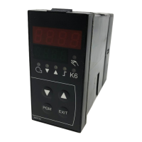
Do you have a question about the Siemens RS-485 and is the answer not in the manual?
| Interface Type | RS-485 |
|---|---|
| Data Rate | Up to 10 Mbps |
| Maximum Cable Length | 1200 meters (at 100 kbps) |
| Number of Devices/Nodes | Up to 32 devices (without repeaters) |
| Topology | Bus |
| Differential Voltage | 1.5V to 5V |
| Common Mode Voltage | -7V to +12V |
| Humidity | 5% to 95% (non-condensing) |
| Communication Protocol | Modbus, Profibus, others |
Communication between PC (master) and device (slave) via MOD bus protocol.
Describes the structure of the transmitted byte, including data word, parity, and stop bits.
Slaves' device addresses range from 1 to 99. Address 0 is reserved for broadcast.
Defines character transmission time calculation based on Baud rate and data format.
Illustrates waiting time calculation for data query/reply based on baud rate and data format.
Illustrates the timing of a data query, including master and slave responses and delays.
Master must not query during slave's internal handling or response time to avoid data issues.
Defines the standard structure of all data blocks: Slave address, Function code, Data field, and Checksum.
Lists 3 error codes and describes the reply format in case of a fault.
Lists conditions under which the slave does not reply, such as incorrect checksum.
Explains the CRC16 calculation method used to detect transmission errors.
Shows examples of CRC16 calculation for data queries and replies.
Defines the data block structure for reading multiple words from a specific address.
Defines the data block structure for writing a single word, including instruction and reply.
Defines the data block structure for writing multiple words, including instruction and reply.
Explains transmission of character ('char') and floating-point ('float') data types.
Lists addresses, data types, access, and parameters for process data.
Lists addresses, data types, access, and parameters for parameter and configuration settings.
Lists parameters related to remote operation modes, including activation and setpoint control.
Describes bit assignments for outputs and states in device status words (0x0200).
Describes bit assignments for binary signals and hardware identification (0x0201).
Introduces operating modes (LOCAL, REMOTE SETPOINT, FULLY REMOTE) and parameter <<RemoteStatus>>.
Lists parameters relevant to remote operation that are stored in RAM.




 Loading...