Building Technologies 2017-11-27
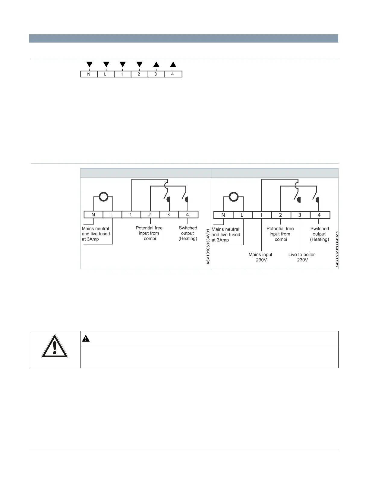
Diagrams
L Live, AC 230 V
N Neutral, AC 230 V
1 Switching input, hot water (HW)
2 Switching input, central heating (CH)
3 Switching output, hot water (HW), normally open (NO), voltage-free contact
4 Switching output, hot water (CH), normally open (NO), voltage-free contact
Shutdown of heating ONLY when service due Shutdown of heating and hot water when service due
Note:
● If AC 230 V direct mains switching is required, link L to 2.
● The voltage applied to terminal 2 is switched to terminal 4 when RWB is in the ON position.
● If wiring up as Service Interval Reminder for a combi-boiler, a new backplate supplied must
be used.
WARNING
The mains supply must be isolated before replacing an existing timeswitch.
Failure to do so may cause damage to the RWB and will invalidate any warranty claims.