Interrupter/Operator Description
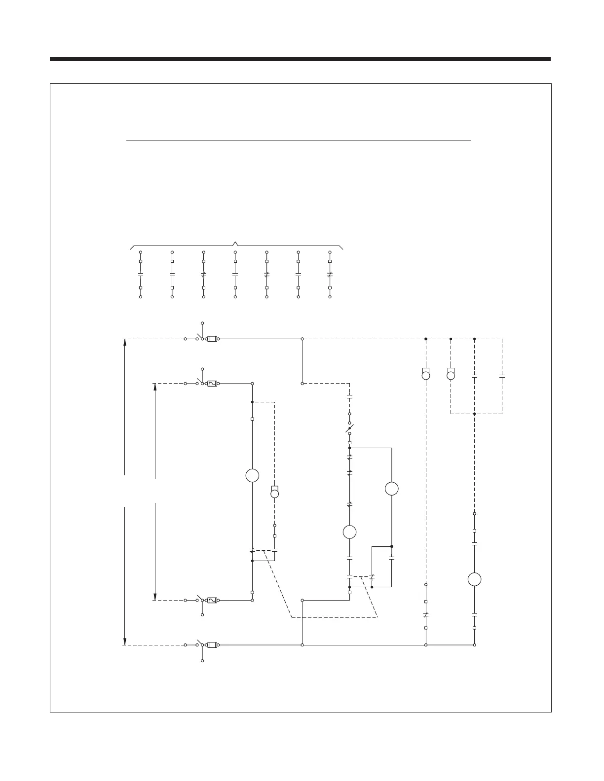
Figure 20a. AC and DC Control Power (Reclosing).
19
(-)
(+)
Prot Relays
2
1
2
1
2
NO
TPX
LS1
C C
NC
LS1
TPX 5
LS2
C
NC
LS2
C
NO
TPX
23
1
2
88
1
LS3
C
NO
32
52Y
31
22
3TPX
52b
52Y
21
4
TPX 4
3
2
7
69
1
14
13
52Y
52
A2
Y
A1
52b Aux Switch, Closed When Bkr OPEN
LEGEND
52Y Anti Pump
52 SRC
Closing, Spring Release Coil
88 Motor
69 Closing Cutout Switch
52T Trip
52a Aux Switch, Open When Bkr OPEN
TPX Terminal Block
W White Indicating Light (Remote)
LS3 Trip Latch Check
LS2 Spring Charged
LS1 Motor Cutoff
14
TPX
8
TPX
7
52
10
b
9
13
52
10
TPX
5
8
a
52
T
2
6
1
2
1
TPX
a
52
7
9
TPX
TPX11
12
16
52
15
12
TPX
TPX
11
a
52 a & b Spare Contacts
52
16
TPX
52
15
15
TPX
a
16
18
TPX
54
17
17
TPX
52
b
18
51 53
TPX
TPX
22
TPX
56
19
21
TPX
52
a
20
24
58
21
22
23
52
b
55 57
27
TPX
28
TPX
26
23
60
52
24
25
a
62
25
52
b
26
59
61
2
08 Motor Power Disconnect
11
1
08
10A
12
3
08
10A
4
5
12
6
08T Close & Trip Power Disconnect
08T
15A
21
12
42
15A
3
08T
4
41
22
5
31
32
01/C Control Switch Close (Remote)
G Green Light (Remote)
R Red Light (Remote)
01
C
01
T
ACDC
3
5
4
6
W
R
2
1
SRC
52
G
R
R
R
Notes on Schematic Arrangement
Schematics are shown with:
1. Closing Springs Discharged
2. Breaker Open
Note that, in this condition, the trip
latch is free to reset, but is tempo-
rarily blocked until the closing springs
are partially recharged. Prior to full
spring charge, LS3 (NO) closes, and
LS3 (NC) opens.
01/T Control Switch Trip (Remote)
Power
Supply
Power
Supply