Connector assignment
6 Edition 05.95 Siemens AG Dk-Nr. 283641
SIMADYN D Hardware User Manual
6. Connector assignment
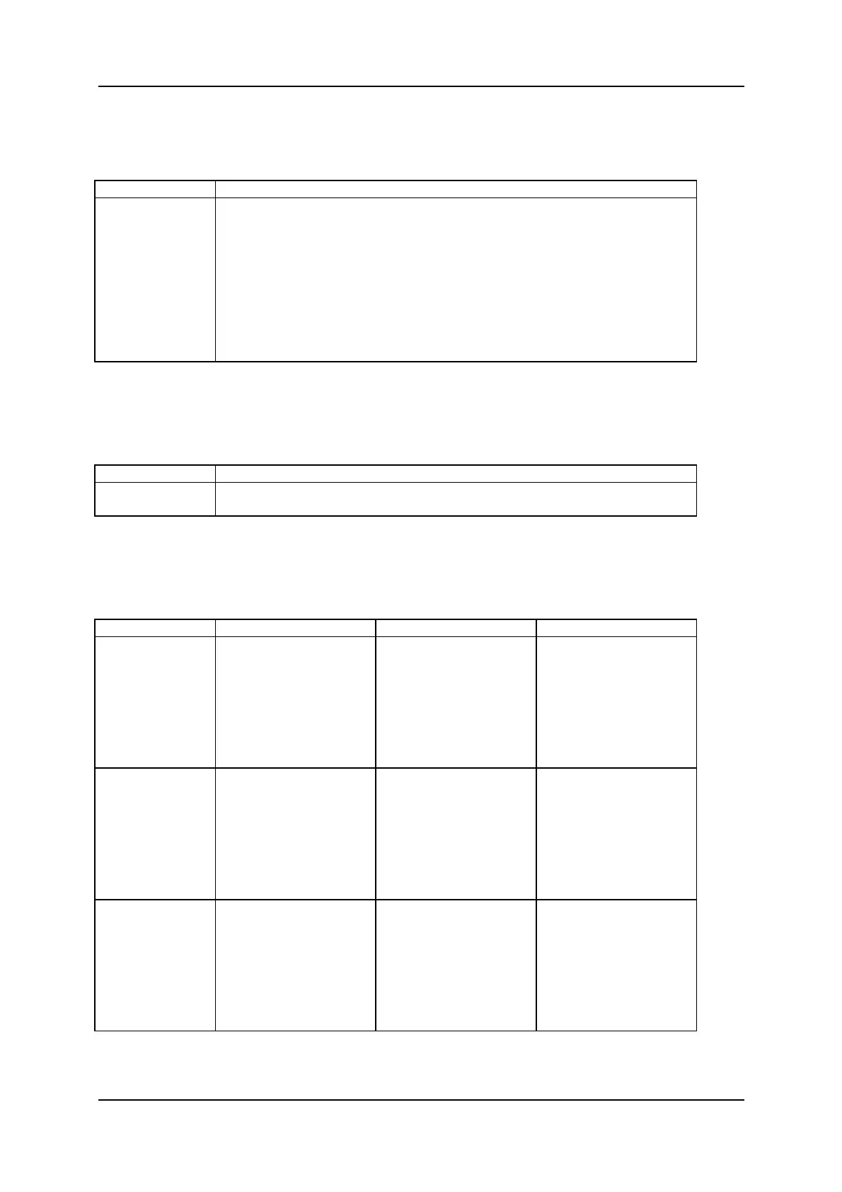
6.1. Assignment of the binary outputs, connector X1
Pin Designation
1
2
3
4
5
6
7
8
9
10
Output 1 ( binary inputs to SIMADYN D )
Output 2
Output 3
Output 4
Output 5
Output 6
Output 7
Output 8
1P ( P24 supply, SIMADYN D side)
1M ( M24 supply SIMADYN D side)
6.2. Assignment of the power supply on the SIMADYN D side, terminal blockX3
Terminal Designation
1P
1M
P24 ( P24 supply SIMADYN D side)
M24 ( M2 supply SIMADYN D side)
6.3. Assignment of the binary inputs, terminal block X2
Terminal Version 1 Version 2 Channel number
1
2
3
4
5
6
7
8
+24V input
+24V input
+24V input
+24V input
+24V input
+24V input
+24V input
+24V input
Channel 1
Channel 2
Channel 3
Channel 4
Channel 5
Channel 6
Channel 7
Channel 8
11
12
13
14
15
16
17
18
+48V input
+48V input
+48V input
+48V input
+48V input
+48V input
+48V input
+48V input
Channel 1
Channel 2
Channel 3
Channel 4
Channel 5
Channel 6
Channel 7
Channel 8
51
52
53
54
55
56
57
58
Input 24V/48V
Input 24V/48V
Input 24V/48V
Input 24V/48V
Input 24V/48V
Input 24V/48V
Input 24V/48V
Input 24V/48V
2P(+24V)
2P(+24V)
2P(+24V)
2P(+24V)
2P(+24V)
2P(+24V)
2P(+24V)
2P(+24V)
Channel 1
Channel 2
Channel 3
Channel 4
Channel 5
Channel 6
Channel 7
Channel 8

 Loading...


