Connection
6.6 Grounding
SCALANCE WxM766
Operating Instructions, 03/2022, C79000-G8976-C617-03
61
6.6 Grounding
EMC disturbances are diverted to ground via the functional ground. This ensures the
immunity of the data transmission.
The grounding screw is identified by the following symbol for the functional ground
.
Protective earth/functional ground
The connection of the reference potential surface with the protective earth system is
normally in the cabinet close to the power feed-in. This earth conducts fault currents to
ground safely and according to DIN/VDE 0100 is a protective earth to protect people,
animals and property from too high contact voltages.
Apart from the protective earth, there is functional grounding in the cabinet. According to
EN60204-1 (DIN/VDE 0113 T1) electrical circuits must be grounded. The chassis (0 V) is
grounded at one defined point. Here, once again the grounding is implemented with the
lowest leakage resistance to ground in the vicinity of the power feed-in.
With automation components, functional ground also ensures interference-free
operation of a controller. Via the functional ground, interference currents coupled in via
the connecting cables are discharged to ground.
Position
The functional ground is established via a grounding screw.
The connector for the grounding cable is located on the bottom of the device, see ⑤ of
the device description (Page 20)
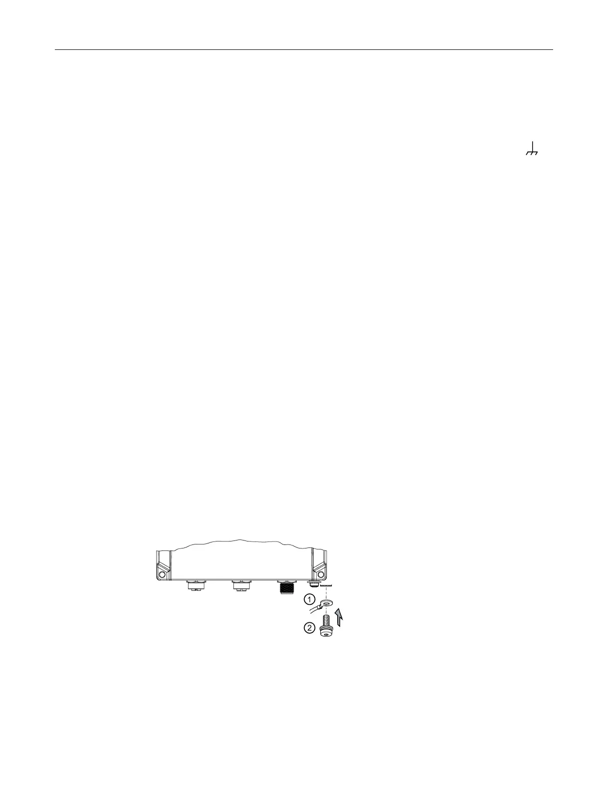
Connecting up functional ground
Follow the steps below to connect the functional ground:
1. Put the grounding terminal ①, and the screw ② together as shown in the drawing.
Grounding terminal with cable
Screw (M4 thread) with spring washer and washer
2. Screw in the screw ② with a maximum tightening torque of 1.5 Nm.
 Loading...


