62
Definition Boxes and The High-Speed Counter Definition (HDEF) instruction assigns
High-Speed Counters the operating mode to a specific high-speed counter (HSCx).
The mode selection defines the clock, direction, start, and
reset functions of the high-speed counter. High-speed counters
can be defined by the definition box to operate in any of the
12 available modes. Not all counters can operate in all of the
available modes, however. Refer to the S7-200 System Manual
for definitions available for each counter.
The High-Speed Counter (HSC) instruction configures and
controls a specific high-speed counter based upon the state of
the special HSC bits. The N parameter specifies the high-speed
counter number. Each counter has dedicated inputs for clocks,
direction control, reset, and start, where these functions are
supported.
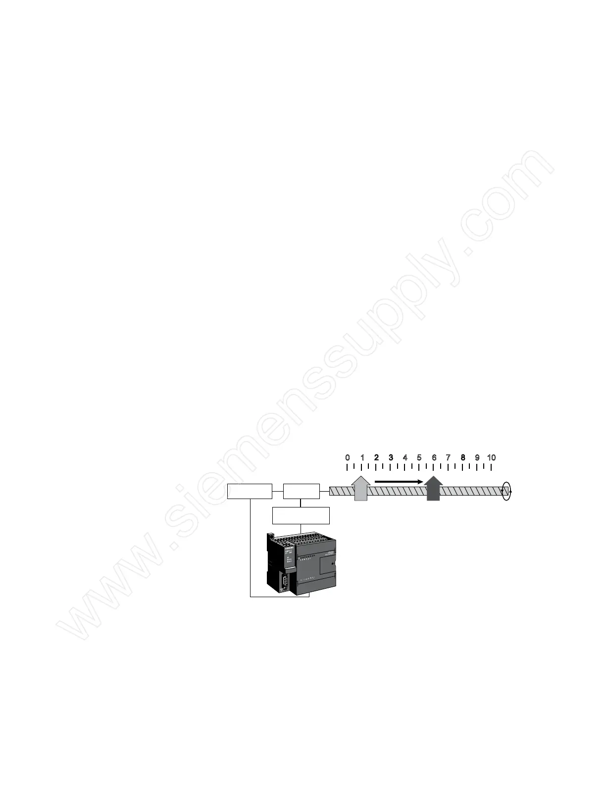
Positioning Example Positioning is one example of an application that may require
use of a high-speed counter. In the following illustration, two
PLC discrete outputs (one for forward and one for reverse)
control a reversing motor starter, which, in turn, controls a
motor.
The motor shaft is connected to an encoder and to a positioning
screw. A platform mounted on the positioning screw moves
away from position 0 as the motor turns in the forward direction
and towards position 0 as the motor turns in the reverse
direction. Pulses from the encoder are connected to PLC inputs
associated with a high speed counter.
1 2 3 4 5 6 7 8 9 100
Encoder
Motor
Reversing
Motor Starter
SF/DIAG
212-1BB
23-0XB0
In this example, the high-speed counter is programmed to
move the platform from position 1 to position 6 and later to
return to position 1. These positions could be associated with
manufacturing operations performed on a part mounted on the
platform.
 Loading...


