Function descriptions 02.00
9-8 SIEMENS AG 6RX1700-0AD76
SIMOREG DC Master Operating Instructions
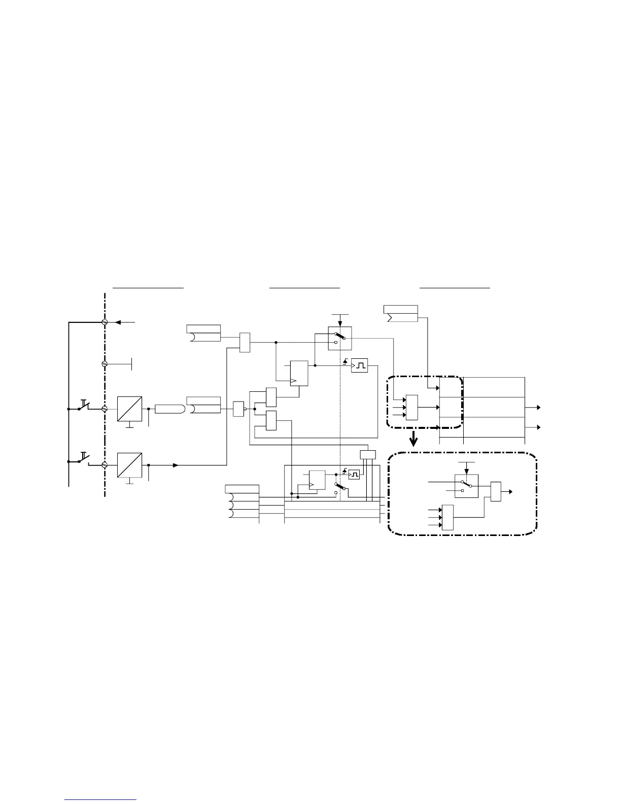
P445 = 1: Edge triggering of "Switch-on command of ON / OFF1":
The switch-on command is stored on the 0
→ 1 transition (see Section 8, Sheet G130).
The binector selected in P444 must be in the log. "1" state. The memory is reset when this
binector switches to the log. "0" state.
In the following example circuit, the ON key (NO contact) is connected to terminal 37 and the shutdown
key (NC contact) to terminal 36. Connector 3003 (= word 3 of DPRAM interface on board in slot 2) is
used as control word 1.
The following parameter values must be set:
P444=10 Connects binector 10 (= status of terminal 36) to the reset input of the memory for the ON
signal (and to the reset input of the memory for the CRAWL command)
P445=1 Selects edge triggering of "Switch-on command of ON / OFF1" (and injection of the
crawling setpoint)
P648=3003 Connector K3003 is assigned status of control word 1.
The combination of the control bit for ON/OFF from the DPRAM control word (K3003.bit0 in this
example) and the switch-on command from the converter terminal is shown in the boxes with dot-dash
line borders.
P24_S
34
24V
5V
36
M
M
35
24V
5V
37
M
B0010
.01
.02
.03
DQ
R
1
1
1
0
<1>
&
D
Q
R
1
1
≥
1
≥
1
0
1
≥
....
<1>
P440 (0)
B
B
B
P444.B (0)
B
P445 = 1
P654.B (1)
B
10
1
≥
P648.B (9)
K
3003
1
≥
&
9
=9/
1
P648
CUD1
Switch-on / shutdown
Selection for
shutdown
Selection for
switch-onn / shutdown
Select
injection of
crawing setpoint
Level /
Edge
Bit No.
0=OFF1
, Shutdown
1=ON, op. cond.
Meaning
(When P648 = 9 bit-serial
input of control bits)
Switch-on c.
of ON/OFF1
ON
Shut-
down
Control word 1
Switch-on comm.
of ON/OFF1
Control
word
bit 0
Section 8, Sheet G110 Section 8, Sheet G130 Section 8, Sheet G180
Bit 0
Bit 1
K3003.bit0
Sequence of operations for switching on drive:
1. Enter the "Switch-on" command (e.g. via terminal "Switch-on/shutdown”)
2. The converter exits operating state 07
3. The "Line contactor closed" relay picks up
4. The field current reduction command is cancelled
If "Enable operation" signal is applied:
5. With a positive brake release time (P087), output signal "Release holding or operating brake"
(binector B0250 = 1) and wait for P087 in operating state 01.0,
with a negative brake release time (PO87 negative), go to step 6 immediately, brake remains
closed (binector B0250 = 0)
6. Technology controller, ramp-function generator, n controller and I controller are enabled
7. When a negative brake release time (P087) has run down, output signal "Release holding or
operating brake" (binector B0250 = 1).
 Loading...


