Getriebe − Nocken − Endschalter Reihe 51 / 51 DZ
Geared Cam Limit Switches Series 51 / 51 DZ
24
Datum / Date 10.2008
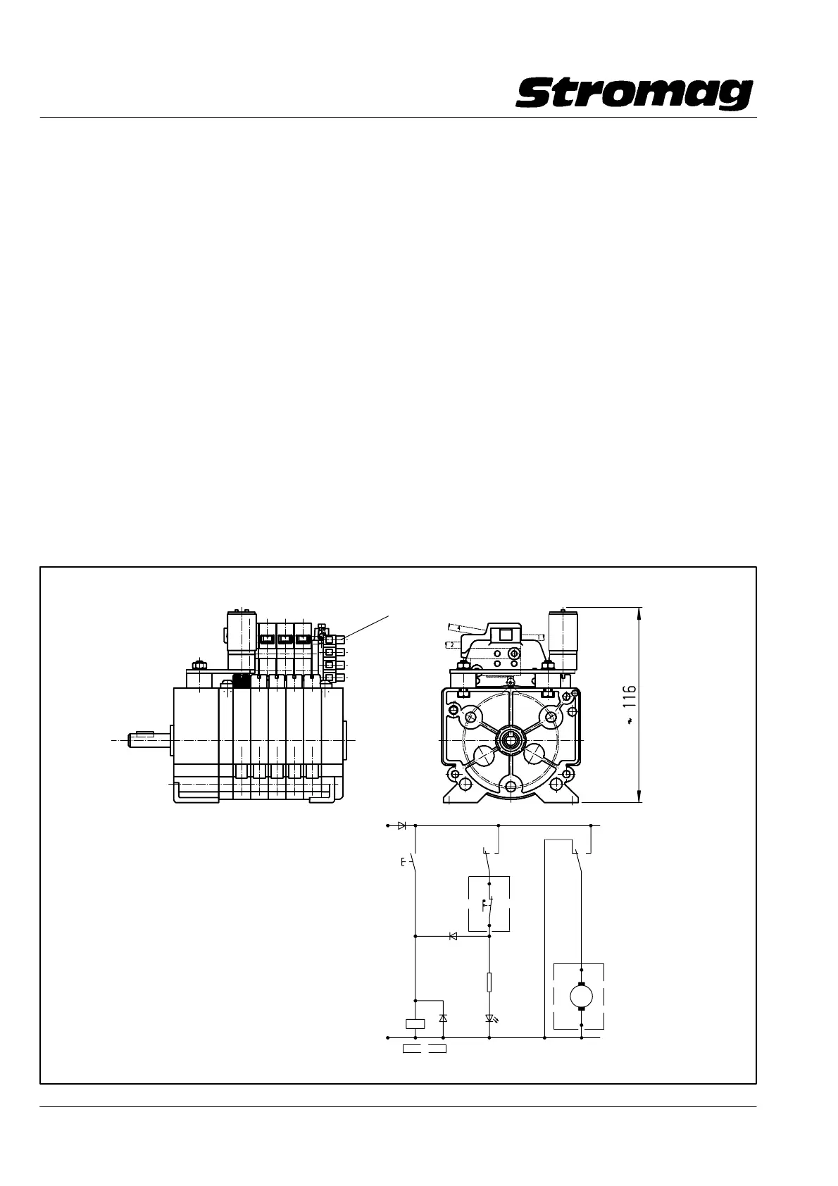
2.6 Motorische Blockverstellung (nur bei Reihe 51)
Durch die Möglichkeit, alle Kontakte mit einer einzigen Ver−
stellschnecke zu verstellen, bietet sich die Möglichkeit, diese
Verstellung mittels eines kleinen Getriebe − Motors zu auto −
matisieren. Einer der eingebauten Schaltkontakte wird dabei
zur Abschaltung des Verstellmotors verwendet. Damit lassen
sich nach einer Verstellung des Antriebssystemes und einer
anschließenden Referenzfahrt alle Kontakte wieder in eine
vorbestimmte Position zu diesem Motorabschaltkontakt brin−
gen. Eingesetzt werden kann dieses System z. B. nach einem
Seilwechsel bei Kranen und Schrappern. Nach dem Seil−
wechsel wird das Lastaufnahmemittel per Hand in eine vorge−
gebene Position gefahren. Durch Knopfdruck wird der Ver−
stellvorgang gestartet. Sobald die Nockenscheibe den
Motorabschaltkontakt (Selbsthaltung der Verstellung) betätigt,
wird der Verstellvorgang gestoppt. Alle Abschaltpunkte der
Maschine stehen jetzt wieder in dem vorherigen Verhältnis
zum Referenzpunkt. Auch mit der Potikupplung "N" ange−
baute Potentiometer werden mitverstellt, siehe dazu Einbau−
bild und Schaltungsvorschlag.
Dieses System kann auch in verstellbaren Punktzügen von
bühnentechnischen Einrichtungen eingesetzt werden. Dabei
ist zu beachten, daß durch die Verstellung der Nockenschei−
ben die Antriebswelle, und damit evtl. dort angebaute Enco−
der, nicht mit verstellt werden.
Dieser ist gesondert nachzujustieren.
2.6 Motor − driven block adjustment (only for series 51)
The possibility to adjust all contacts with a single adjusting
worm offers the option of automating this adjustment by
means of a small geared motor. One of the switching contacts
provided is used for disconnection of the adjusting motor. Af−
ter adjustment of the drive system and subsequent reference
operation, all contacts can be reset to a predetermined posi−
tion with respect to this motor disconnecting contact. This sy−
stem can be used, e.g. after a rope change for cranes and
scrapers. After the rope change, the lifting appliance is moved
into a predetermined position manually. Adjustment can be
initiated by pressing a button. Adjustment is stopped as soon
as the cam disc actuates the cam disc of the motor discon−
necting contact (self − holding of adjustment). All disconnec−
ting points of the machine are now placed in their previous
relation to the reference point. Potentiometers with the poten−
tiometer coupling "N" are also adjusted, see installation dia−
gram and circuit suggestion.
This system is also suitable for use in adjustable stage machi−
nery, whereby it is important to ensure that the drive shaft and
in turn a possibly installed encoder is not affected through
adjustment of the cam discs.
The encoder has to be re − adjusted separately.
DD1_40292V
Klemmleiste/Terminal strip − X1
Technische Daten / Technical data:
Anschlußspannung (Motor)
Supply voltage (motor) 24V DC
Stromaufnahme (Motor)
Current consumption (motor) ca. 200mA
Anschlußwiderstand
Connection resistance 65 Ohm
max. Verstellzeit
max. adjustment time ca.90 sek.
S2
+ 24V
0 V
M
R1
V3
LED
1k
M1
im Endschalter eingebaut / mounted into the limit switch
− X1.2
− X1.1
S1
K1K1
K1
V1
V3
1N4007
1N4007
1N4007
−A1
−A2
− X1.4
− X1.3
V2
DD1_40296V