Supplementary system components
6.4 CBE30-2 Ethernet communication board
SIMOTION D4x5-2
110 Manual, 02/2012
Interface assignment
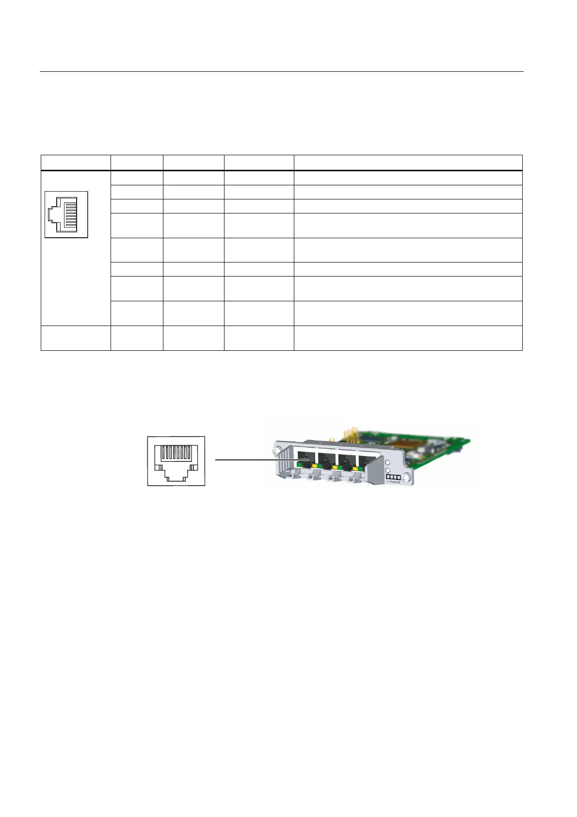
Table 6- 14 X1400 interface
Representation Pin Name Signal type Description
1 TXP Output Ethernet transmit differential signal
2 TXN Output Ethernet transmit differential signal
3 RXP Input Ethernet receive differential signal
4 -- 4 together with 5 via 75 ohm at the 1 nF capacitor to the
shield ground
5 -- 4 together with 5 via 75 ohm at the 1 nF capacitor to the
shield ground
6 RXN Input Ethernet receive differential signal
7 -- 7 together with 8 via 75 ohm at the 1 nF capacitor to the
shield ground
8 -- 7 together with 8 via 75 ohm at the 1 nF capacitor to the
shield ground
Screened
backshell
M_EXT Screen, permanently connected
Position of the ports
The interfaces are located on the front side of the CBE30-2.
Figure 6-10 CBE30-2 interface

 Loading...


