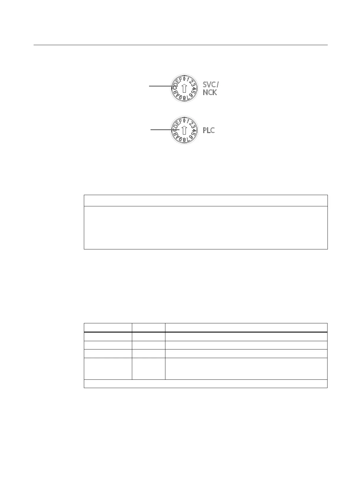
0RGHVHOHFWRUVZLWFK
6HUYLFHVHOHFWRUVZLWFK
Figure 3-3 Selector switches for service and operating modes of the SIMOTION D4x5-2
NOTICE
Damage from electrostatic discharge
The rotary switch can be destroyed by static electricity.
Operate the rotary switch only with an insulated screwdriver.
Comply with the ESD rules.
Mode switch
The following table contains the possible mode switch positions and the associated LED
displays.
The mode switch positions are explained in the order in which they are arranged on
the SIMOTION D4x5‑2.
Table 3-1 Mode switch position
Switch position Meaning LED
0 RUN RUN
1 STOPU SU/PF
2 STOP STOP
3 MRES The MRES operating states are indicated via the STOP LED. (on/
off/flashing, see
SIMOTION D4x5‑2
Commissioning and Hardware
Installation Manual)
Other selector positions are not assigned
The following table contains the states of the SIMOTION D4x5‑2 that can be set via the mode
switch.
Operator control (hardware)
3.2 Operator controls
SIMOTION D4x5-2
Manual, 04/2014 45