12.98 Connecting-up
Siemens AG 6SE7087-7NP87-2DD0
SIMOVERT MASTERDRIVES Operating Instructions 5-3
The DC link bus module is used to transfer energy between the
capacitor module and the connected inverters.
Bar Designation Meaning Range
3 PE3 Protective conductor connection
2 D / L- DC link voltage - DC 510 - 650 V
1 C / L+ DC link voltage + DC 510 - 650 V
Connectable cross-section: “Electro-plated copper" 3x10 mm, rounded
off according to DIN 46433.
Bar 1 is at the front when installed.
Table 5-1 DC link bus module
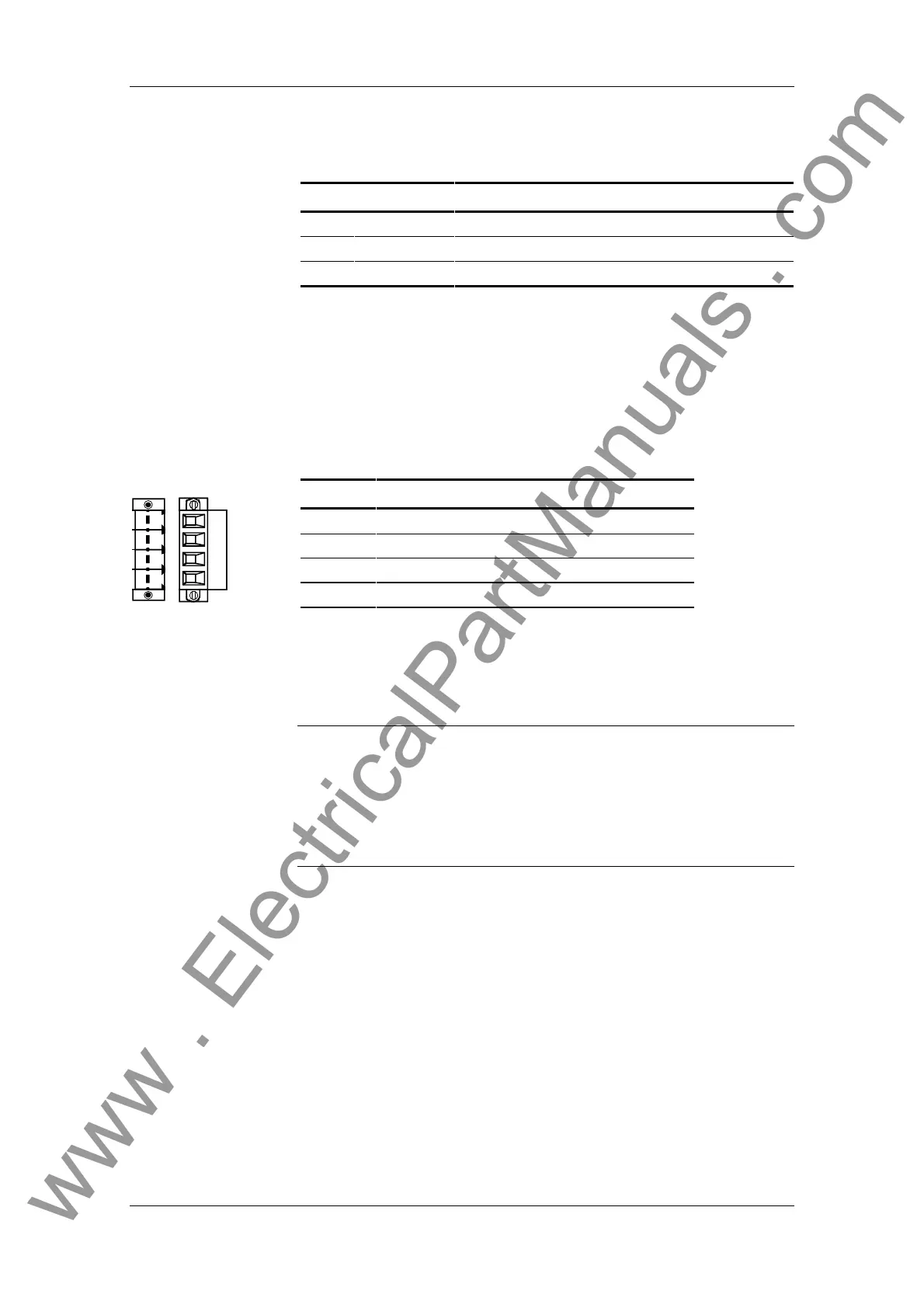
The connections are used for pre-charging the buffer capacitors.
The two remaining free contacts are used for looping the pre-charging
cable to other capacitor modules.
Terminal Meaning Range
C’ + Terminal of pre-charging DC 510 V - 650 V
C’ + Terminal of pre-charging DC 510 V - 650 V
D’ - Terminal of pre-charging DC 510 V - 650 V
D’ - Terminal of pre-charging DC 510 V - 650 V
Connectable cross-section: 4 mm² (AWG 10)
Terminal D’ is at the front when installed.
Table 5-2 Pre-charging connection
♦
During operation, the full DC link voltage is always present at the
terminals for pre-charging the capacitor module.
♦
During pre-charging, the charging current of all connected capacitor
modules flows via the terminals.
♦
For reasons of protection, cables with 4 mm² Cu must be used at
connection X7!
X3 - DC link bus
module
X7 - Pre-charging
C’ D’ D’C’
NOTES
www . ElectricalPartManuals . com
 Loading...