Implementation
4.3 Model structure
SINAMICS PCS simulation model
18 Operating Instructions, 10/2020, A5E50173895A
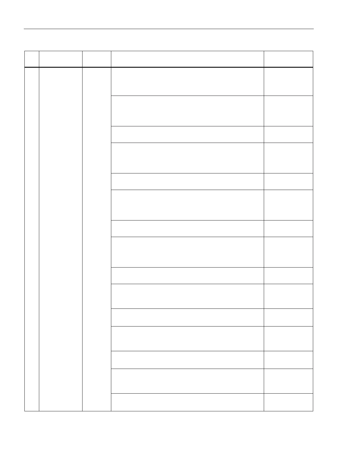
No. Name Input/
Description Value range
The relative limit values and response times for grid monitoring
are specified at this input.
All voltage limit values are referred to the rms grid voltage.
All frequency limit values are referred to the grid frequency.
• U>>_Limit
The protection function responds if the rms value of a phase-
to-phase voltage exceeds this limit value for more than time
U>>_Zeit.
• U>>_Zeit
35 ms … 100 ms
• U>_Limit
The protection function responds if the rms value of a phase-
to-phase voltage exceeds this limit value for more than time
U>_Zeit.
• U>_Zeit
35 ms ...
180000 ms
• U<<_Limit
The protection function responds if the rms value of a phase-
to-phase voltage falls below this limit value for more than
time U<<_Zeit.
• U<<_Zeit
35 ms ... 800 ms
• U<_Limit
The protection function responds if the rms value of a phase-
to-phase voltage falls below this limit value for more than
time U<_Zeit.
• U<_Zeit
35 ms ... 2400 ms
• f>>_Limit
The protection function responds if the grid frequency ex-
ceeds this limit for more than time f>>_Zeit.
• f>>_Zeit
Delay time for f>>_Limit
40 ms ... 100 ms
• f>_Limit
The protection function responds if the grid frequency ex-
ceeds this limit for more than time f>_Zeit.
• f>_Zeit
Delay time for f>_Limit
40 ms ... 5000 ms
• f<_Limit
The protection function responds if the grid frequency ex-
ceeds this limit for more than time f<_Zeit.
• f<_Zeit
Delay time for f<_Limit
40 ms ... 100 ms