Preface 11.02
VIII
Siemens AG, 2002. All rights reserved
SINUMERIK 840D/840Di/810D Diagnostics Guide (DA) – 11.02 Edition
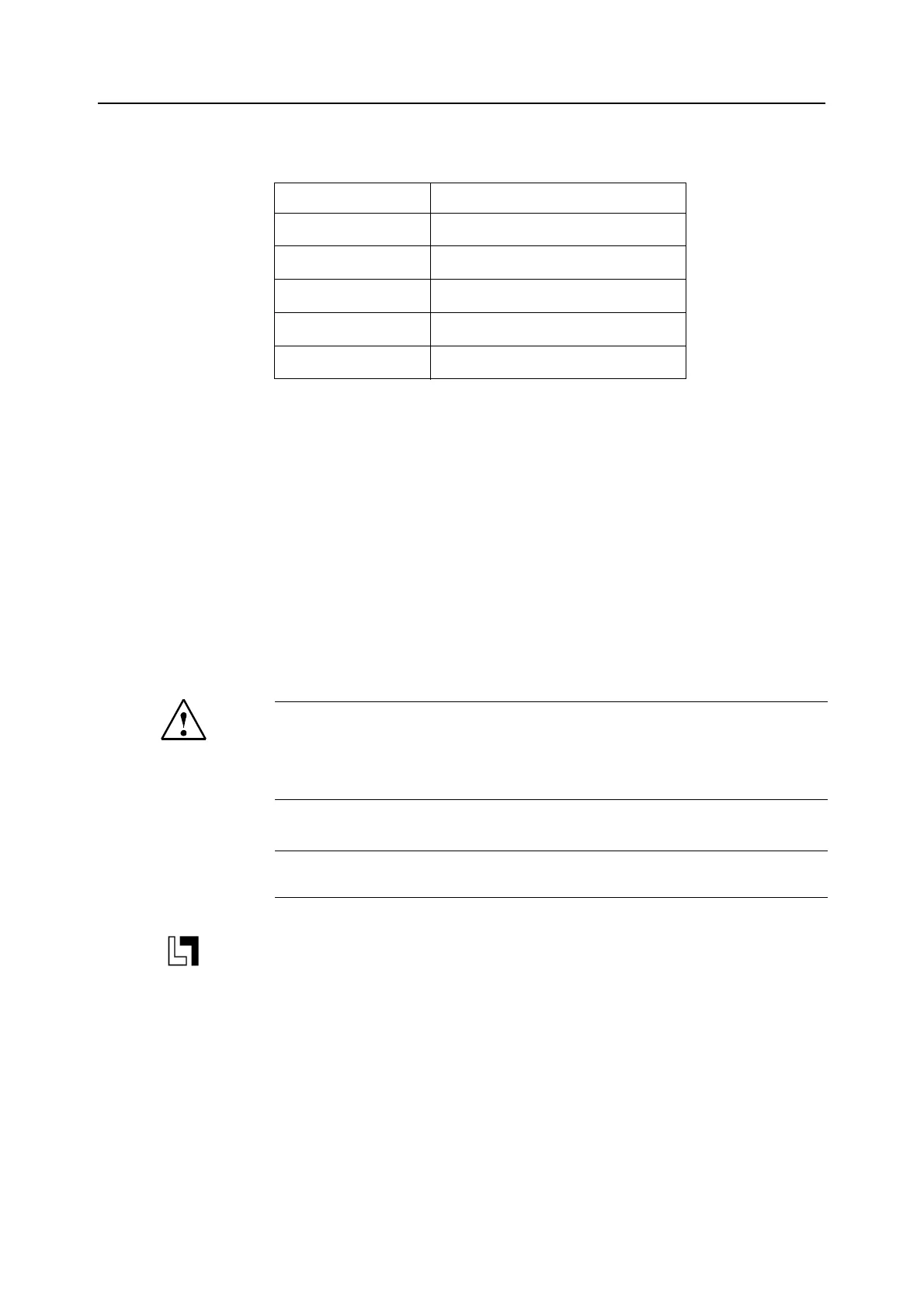
PLC alarms/messages Table 1_4 Alarm number ranges, continued
1)
More detailed information is available via the diagnostics function (diagnostics buffer) of
SIMATIC STEP 7.
2)
The PLC alarms in the range 500000 - 899999 are configured and described by the
machine manufacturer.
Action list The actions described in the alarm texts ("Action %---") are explained in detail in the table
in the "Action list" section.
Search helps For better orientation, you are provided with a table of contents as well as the appendices:
• Abbreviations
• List of References.
Safety
Explanation of symbols
Ordering data supplement
This symbol appears in this documentation whenever a described function is not con-
tained in the standard scope of supply and has to be ordered as an option.
400000 - 499999 General alarms
500000 - 599999
Channel alarms
2)
600000 - 699999
Axis/spindle alarms
2)
700000 - 799999
User area
2)
800000 - 899999
Sequencers/graphs
2)
(810001 - 810009
System error messages from PLC
1)
)
Danger
Please check the situation at the system very carefully on the basis of the description
of the alarms that have occurred. Eliminate the causes for the occurrence of the alarms
and acknowledge in the manner indicated. Otherwise, the machine, workpiece, stored
settings and possibly your health are at risk.
!
Important
This notice indicates that important facts have to be taken into consideration.

 Loading...


