Read and understand these instructions before installing, operating, or maintai-
ning the equipment.
The relay must be installed in switchgear cubicles complying with degree
of protection IP32, IP43 or IP54, depending on the prevailing environmental
conditions.
The products described herein are designed to be components of a customized
machinery safety-oriented control system. A complete safety-oriented system
may include safety sensors, evaluators, actuators and signaling components. It
is the responsibility of each company to conduct its own evalution of the effecti-
veness of the safety system by trained individuals. Siemens AG, its subsidiaries
and affiliates (collectively "Siemens") are not in a position to evaluate all of the
characteristics of a given system or product or machine not designed by
SIEMENS.
Siemens accepts no liability for any recommendation that may be implied or
stated herein. The warranty contained in the contract of sale by Siemens is the
sole warranty of Siemens. Any statements contained herein do not create new
warranties or modify existing ones.
You can use the safety relay 3TK2822 in safety circuits as per VDE 0113 Part 1
(11.98) or EN 60 204-1 (11.98), e.g. with movable covers and guard doors; the
safety relay 3TK2823 in EMERGENCY STOP devices as per EN 418. Depending on
external connections, category 4 as per DIN EN 954-1 is achievable.
The safety relays 3TK2822/23 have two release circuits (safety circuits) configu-
red as NO circuits. The number of release circuits can be increased by adding
one or more 3TK2830 extension modules. Three LEDs indicate operating state
and function.
When the EMERGENCY STOP button or the limit switch is unlocked and when
the ON button is pressed, the internal circuit of the safety relay and the external
contactors are checked for proper functioning.
On the 3TK2823, the ON circuit Y33, Y34 is checked for short-circuit. This means
that a fault is detected when Y33, Y34 is closed before the EMERGENCY STOP
button is closed.
Connect the EMERGENCY STOP button or the limit switch to terminals Y11, Y12,
Y21, Y22. Connect the ON button in series with the NC contacts of the external
contactors (feedback circuit) to terminals Y33, Y34.
Be sure to fit the specified fuses. Otherwise safe interruption
in the event of a fault cannot be guaranteed.
For further data and accessories see Catalog.
Reliable functioning of the equipment is only ensured with certified compon-
ents.
DANGER
Hazardous voltage.
Will cause death or serious injury.
Disconnect power before working on
equipment
IMPORTANT NOTICE
Application
Functions and connections
Terminal
assignments
Operating
voltage
A1
A2
L/+
N/-
Sensors Y11, Y12
Y21, Y22
Y33, Y34
Channel 1 EMERGENCY STOP or limit switch
Channel 2 EMERGENCY STOP or limit switch
ON button, feedback circuit
Outputs 13, 14
23, 24
Release circuit 1 (NO)
Release circuit 2 (NO)
Cable
lengths
for 2 x 1.5 mm
2
max. 1000 m (total cable length for
sensors and power supply lines)
Figures Fig. I: Dimension drawings (dimensions in mm)
Fig. II: Installation/Cage Clamp
Fig. III: Internal circuit: ¿ PTC fuse
À Power pack
Á Control logic
 Channel 1
à Channel 2
Fig. IV: 3TK2822 with Autostart for guard door monitoring,
category 4 per EN 954-1
Fig. V: 3TK2823 with monitored start for EMERGENCY STOP,
category 4 per EN 954-1
!
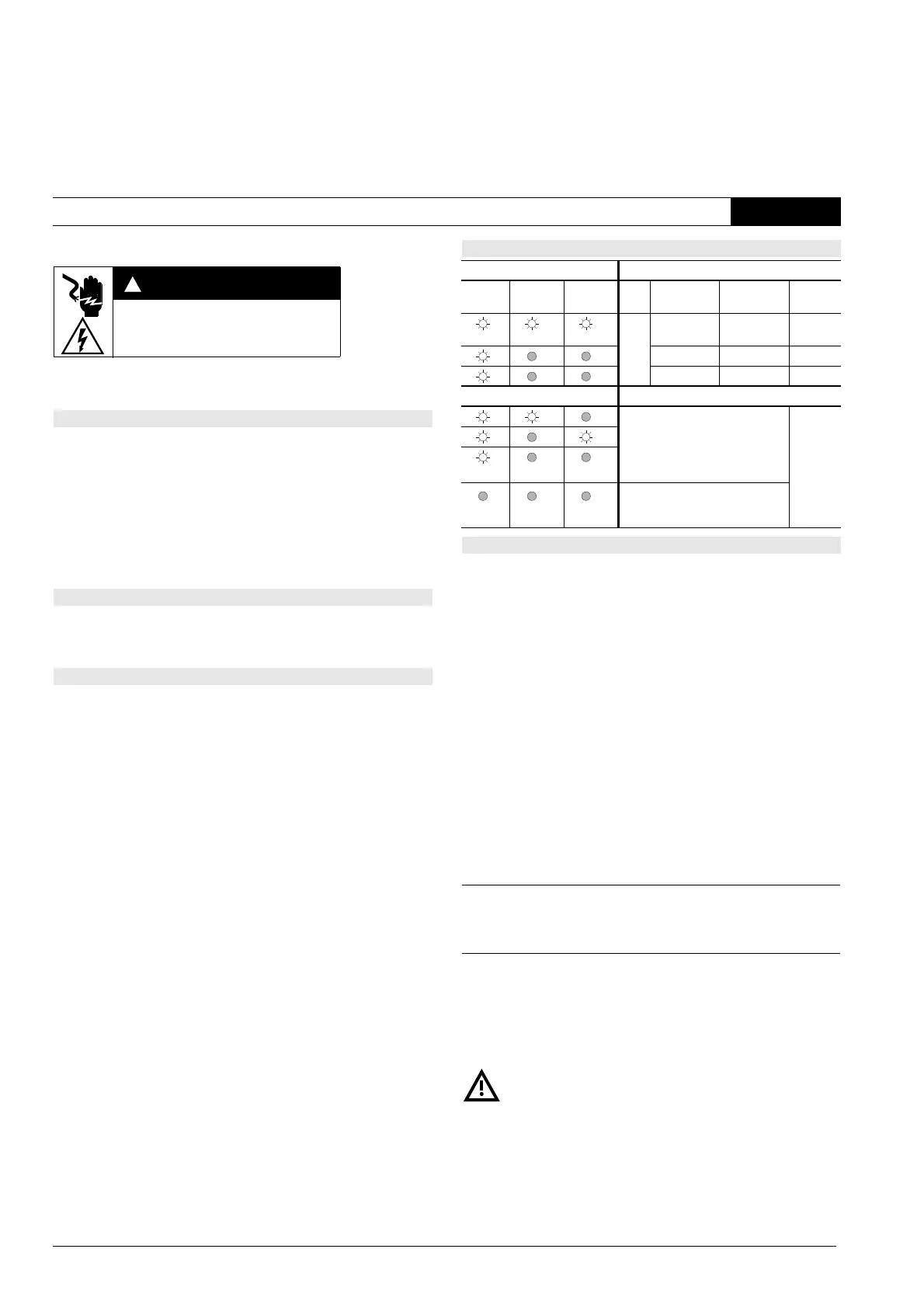
Operating states
LED Operation
POWER Channel 1 Channel 2 PS EMERGENCY
STOP
ON Release
circuits
ON not activated activated closed
activated not activated open
not activated not activated open
Faults
• Relay fusion-welded
• Motor contactor fusion-welded
• Defect in electronics
• Short-circuit in ON circuit
(only with 3TK2823)
open
Cross or ground faults in
EMERGENCY STOP circuit (min. fault
current I
Kmin
= 0.5 A; PTC fuse trips)
Technical data
Permissible ambient temperature T
u
Operation/storage –25 to +60 °C/–40 to +80 °C
Degree of protection to EN 60 529 IP40, IP20 at terminals
Rated insulation voltage U
i
300 V
Rated impulse withstand voltage U
imp
4 kV
Rated control supply voltage U
s
24 V AC/DC
Rated power 1.5 W
DC operating range 0.85 to 1.2 x U
s
AC operating range 0.85 to 1.1 x U
s
Shock resistance (half-sine) as per IEC 60068 8 g/10 ms
Weight 0.240 kg
Recovery time after EMERGENCY STOP 3TK2822
3TK2823
minimum 200 ms
minimum 400 ms
Release time after EMERGENCY STOP max. 20 ms
Response time 3TK2822
3TK2823
max. 80 ms
max. 30 ms
Utilization
category
as per DIN VDE 0660
Part 200, IEC 60947-5-1
Rated operational
voltage U
e
(V)
Rated operational current I
e
with all release circuits loaded
(A)
50 °C 60 °C 70 °C
AC-15 230 5 4.5 4
DC-13 24 5 4.5 4
115 0.2 0.2 0.2
230 0.1 0.1 0.1
Continuous current I
th
54.54
Short-circuit
protection for
release circuit
Fuse links DIAZED
Duty class gL(gG)
quick response
6 A
10 A
The safety relay is protected by an internal self-healing PTC
fuse (multifuse).
2
SIRIUS 3TK2822, 3TK2823
Safety Relay
DIN EN 60 947-5-1 (08.00)
Operating Instructions Order No.: 3ZX1012-0TK28-2CA1
English
 Loading...