© Siemens AG, DE-90475 Nuremberg, Germany. All rights reserved.
SITOP PSU100L-02-XA19, 10.2022
1
-1LB00 24 V/20 A
Betriebsanleitung (kompakt)
Operating Instructions (compact)
Instrucciones de servicio (resumidas)
操作说明 (精简版)
Notice de service (compacte)
Istruzioni operative (descrizione sintetica)
Руководство по эксплуатации (компактное)
İşletme kılavuzu (kısa)
https://support.industry.siemens.com
1: Vista degli apparecchi
Die SITOP-Stromversorgung ist ein Einbaugerät,
Schutzart IP20, Schutzklasse I.
Primär getaktete Stromversorgung zum Anschluss an
1-phasiges Wechselstromnetz (TN-, TT-Netz nach
IEC 60364-1) mit Nennspannungen 100 - 240 V,
50 - 60 Hz; Ausgangsspannung 24 V DC, potenzial-
frei, kurzschluss- und leerlauffest.
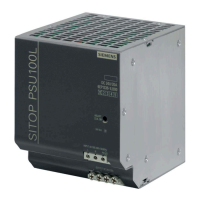
Bild 1 Ansicht Geräte (Seite 1)
Der einwandfreie und sichere Betrieb dieses Gerätes/
Systems setzt sachgemäßen Transport, sachgemäße
Lagerung, Aufstellung und Montage sowie
sorgfältige Bedienung und Instandhaltung voraus.
Dieses Gerät/System darf nur unter Beachtung der
Instruktionen und Warnhinweise der zugehörigen
technischen Dokumentation eingerichtet und
betrieben werden.
Nur qualifiziertes Personal darf das Gerät/System
installieren und in Betrieb setzen.
Montage auf Normprofilschiene TH35-15/7,5
(EN 60715).
Das Gerät ist so zu montieren, dass die Klemmen un-
ten sind.
Unterhalb und oberhalb des Gerätes muss mindes-
tens ein Freiraum von je 50 mm eingehalten werden
(max. Kabelkanaltiefe 50 mm).
Vor Beginn der Installations- oder Instandhaltungs-
arbeiten ist der Hauptschalter der Anlage
auszuschalten und gegen Wiedereinschalten zu
sichern. Bei Nichtbeachtung kann das Berühren
spannungsführender Teile Tod oder schwere
Körperverletzung zur Folge haben.
Die Betätigung des Potenziometers ist nur mittels
isoliertem Schraubendreher zulässig.
Für die Installation der Geräte sind die einschlägigen
länderspezifischen Vorschriften zu beachten.
Wichtiger Hinweis: Eingangsseitig ist ein Lei-
tungs- oder Motorschutzschalter vorzusehen.
Der Anschluss der Versorgungsspannung muss ge-
mäß IEC 60364 ausgeführt werden.
Verwenden sie Kupferdraht zugelassen für 60/75 °C.
Bei Betrieb an 2 Außenleiterspannungen ist eine ge-
eignete Absicherung bei Klemme N notwendig.
Bild 3 Klemmendaten (Seite 2)
*1)
Endanschlag nicht höher belasten
The SITOP power supply is a built-in unit, degree of
protection IP20, protection class I.
Primary switched-mode power supply for connection to
1-phase AC system (TN, TT system in accordance with
IEC 60364-1) with rated voltages of 100 - 240 V,
50 - 60 Hz; 24 V DC output voltage, isolated, short-cir-
Figure 1 View of devices (Page 1)
Appropriate transport, proper storage, mounting,
and installation, as well as careful operation and
service, are essential for the error-free, safe and
reliable operation of the device/system.
Setup and operation of this device/system are
permitted only if the instructions and warnings of
the associated technical documentation are carefully
observed.
Only qualified personnel are allowed to install the
device/system and commission it.
Mounted on a standard mounting rail TH35-15/7.5
(EN 60715).
The device should be mounted so that the terminals
are at the bottom.
A clearance of at least 50 mm must be maintained
above and below the device (max. cable duct depth
Before starting any installation or maintenance work,
the main system switch must be opened and
measures taken to prevent it from being reclosed. If
this instruction is not observed, touching live parts
can result in death or serious injury.
It is only permissible to use an insulated screwdriver
when actuating the potentiometer.
For installation of the devices, the relevant country-
specific regulations must be observed.
Important note: A miniature circuit breaker or
motor circuit breaker must be provided on the in-
put side.
The supply voltage must be connected according to
IEC 60364.
Use copper wire certified for 60/75 °C.
For operation at 2 line-to-line voltages, a suitable
fuse protection is required at terminal N.
Figure 3 Terminal data (Page 2)
*1)
Do not subject the end stop to any higher stress
ESPAÑOL (ESPAÑA)
Descripción
La fuente de alimentación SITOP es un modelo empotra-
ble con grado de protección IP20 y clase de protección I.
Fuente de alimentación conmutada en primario para la
conexión a la red alterna monofásica (red TN, TT según
IEC 60364-1) con tensiones nominales de 100 - 240 V,
50 - 60 Hz; tensión de salida 24 V DC, aislamiento galvá-
nico, resistente a cortocircuito y a marcha en vacío.
Figura 1 Vista del aparato (Página 1)
El funcionamiento correcto y seguro de este aparato/
sistema presupone un transporte, un almacenamien-
to, una instalación y un montaje adecuados, así
como un manejo y un mantenimiento rigurosos.
Este aparato/sistema debe ajustarse y utilizarse única-
mente teniendo en cuenta las instrucciones y adverten-
cias de la documentación técnica correspondiente.
La instalación y puesta en marcha del
aparato/sistema debe encomendarse exclusivamente
Montaje en perfil normalizado TH35-15/7,5
(EN 60715).
El aparato debe montarse con los bornes en la parte
inferior.
Por encima y por debajo del aparato debe dejarse un
espacio libre de al menos 50 mm (profundidad máx.
del canal de cables 50 mm).
Figura 2 Diseño (Página 2)
Antes de comenzar trabajos de instalación o manteni-
miento, se debe desconectar el interruptor principal de la
instalación y asegurarlo contra una posible reconexión. Si
no se observa esta medida, el contacto con piezas bajo
tensión puede provocar la muerte o lesiones graves.
El potenciómetro solo deberá girarse usando un
destornillador aislado.
A la hora de instalar los aparatos, se deben observar las
disposiciones o normativas específicas de cada país.
Información importante: Por el lado de entrada
debe preverse un automático magnetotérmico o
un guardamotor.
La conexión a la tensión de alimentación debe reali-
zarse conforme a IEC 60364.
Utilice hilo de cobre homologado para 60/75 °C.
Si la fuente se conecta a 2 fases de un sistema trifá-
sico es necesario prever una protección adecuada en
Figura 3 Datos de los bornes (Página 2)
*1)
Carga máxima del tope de fin de carrera
SITOP 电源为内置设备,防护方式为 IP20,防护等级
为 I。
本设备为主时钟电源,用于连接标称电压为
100 - 240 V,50 - 60 Hz 的单相交流供电系统(符合
IEC 60364-1 标准的 TN、TT 电网);输出电压
24 V DC,电位隔离,具有短路保护和空载保护功
存放、装配、安装作业以及仔细谨慎的操作和维护。
在安装和运行本设备前请务必阅读并注意本设备/系统
技术文档中包含的规定和警示。
本设备/系统仅允许由专业技术人员安装和调试。
安装在凹顶导轨 TH35-15/7.5 (EN 60715) 上。
安装设备时应使端子位于下方。
设备的上方和下方必须至少保留各 50 mm 的通风空
间(最大电缆槽深度 50 mm)。
防止设备重新合闸。违反该规定可能会导致作业人员
接触到带电零部件,从而导致严重的人身伤害甚至人
员死亡。
电位计只允许使用绝缘螺丝刀进行操作。
重要提示:设备线路侧必须配备一个小型断路器或保
护用电机断路器。
必须按照 IEC 60364 标准连接供电电压。
使用最高允许 60/75 °C 的铜线。
如具有两种线间电压,那么端子 N 上必须带有合适的
保护装置。