)
Technical Instructions SKP25U.. Pressure Regulating Gas Valve Actuators
Document Number 155-752
July 9, 2014
Page 6 Siemens Building Technologies, Inc.
Installation,
Continued
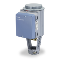
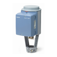
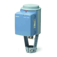
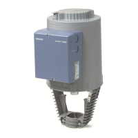
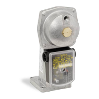
• The SKP25 actuator is directly coupled to the VG series valve body by four
pre-mounted 4 mm Allen key screws.
• The square mounting flange can be rotated in steps of 90
o
to provide four different
mounting positions. The SKP25 actuator can be mounted in any position with the
diaphragm vertical, except upside down.
• The actuator can be mounted or replaced while the valve body is under pressure.
• The SKP25 actuator has two knock-outs for the installation of 1/2”-14 NPSM
conduit connections.
• When conduit routing is connected, flexible conduit must be used.
• Liquid tight conduit must be used in combination with AGA66 to provide NEMA 3,
3R, and 4 protection.
• The terminal marked GND, located above the wiring terminals, must be connected
to the electrical ground.
NOTE: Wiring must meet all relevant electrical codes.
Start-up
Regulator
The gas outlet pressure setpoint adjustment screw is located in the center of the
regulator cover. The SKP25.0 models are available with three interchangeable
setpoint springs for an adjustable range of 0” to 100” WC The SKP25.411U models
are available with two interchangeable setpoint springs for an adjustable range of 1.5 to
20 psi. The bias for the SKP25.611U1 model is adjustable from 0 to 4.0" WC (See
Specifications and Table 2). Clockwise rotation of the setpoint adjustment screw
increases the outlet gas pressure. The hexagonal cap must be tightened after the
setpoint screw has been adjusted and may be sealed from tampering by means of a
wire and lead seal.
When firing at maximum burner capacity, ensure that the SKP25 /VG is
not in the fully open position. If this is the case, either the gas valve is sized
too small or the gas supply pressure is too low.
Wiring and
Switch
Adjustment
(See Terminal
Designations)
• The actuator is equipped with spring-loaded terminals for 14 AWG wires.
• The actuator has two line and two neutral terminals.
• Insert one wire into the opening of the terminal while pressing the lever downward
with a screwdriver or hard object. Make sure that all strands insert into the opening.
• Adjust the auxiliary switch (if provided) according to the wiring diagram on the label
below the terminals (see Figure 2). The adjustment screw and scale are located on
the right side of the terminal box, and are visible through the transparent portion of
the terminal cover.
NOTES: 1. The auxiliary switch is adjustable between 40% and 100% of the stroke.
The factory setting is at 40%.
2. The auxiliary switch must not be used for proof of closure detection or other
safety interlock functions.
3. The Proof of Closure Switch is non-adjustable.
 Loading...