6/26
Building Technologies Division CC1N7817en
24.02.2015
Mechanical design
Lower housing part made of die-cast aluminum
Housing cover made of impact-proof and heat-resistant plastic
Synchronous motor
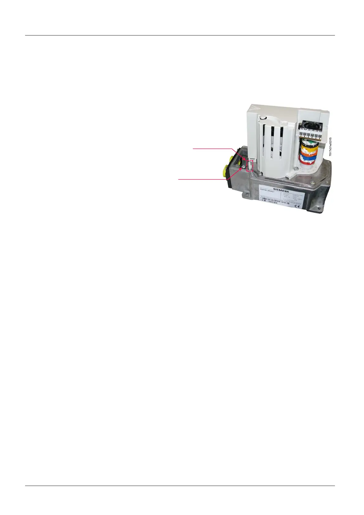
Shaft can be manually disengaged from the motor by operating the coupling
(coupling pin (K1))
Automatic reengagement
Disengagement of drive shaft / motor by pressing coupling pin «K1»
Coupling pin "K1"
Earth terminal „PE“
Earth terminal (PE) with screw fitting
Non-reactive gear
With adjustable cams
Scales beside the cams indicate the angle of the switching point
Internally
– Scale 0...135° at the end of the cam assembly
– Scale range to direction of rotation with arrow marking for SQM41 or with marking
in slot die for SQM40
RAST3.5 screw terminals are factory supplied, depending on the PCB variant
RAST5 screw terminals are factory supplied, depending on the PCB variant
Optional: Insulation displacement connectors
Cable entry by means of 2 openings in the connector cover supplied.
The cable glands are not included in the scope of delivery
Large openings in the housing allow easy cable installation
Maintenance-free gearwheels and bearings.
Different shaft versions available, shafts are supplied assembled
Drive shaft is not replaceable
Mounting holes on the lower side of the housing (shaft side), such as actuators
SQM45... / SQM48... using M5 screws, or alternatively as actuators SQM10... / SQM20...
front mounting using M5 self-tapping screws (see chapter Dimensions).
Housing
Drive motor
Coupling
Earthing connection
Cam shaft drive
djustment of
switching points
Position indicator
Electrical
connections
Gear train
Drive shaft
ctuator fixing
 Loading...