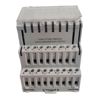
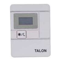
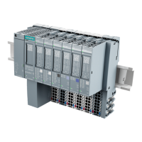
TX-I/O Modules
NOTE:
The 24 Vdc consumption from the modules of field devices other than current
sensors must be counted separately. Admissible current for each TXM1.8X or
TXM1.8X-ML module: 200 mA.
TX-I/O Module Consumption Data
(24 Vdc per I/O point, values in mA for supply sizing)
TXM1.
8X-ML
TXM1.
8X
TXM1.
8U-ML
TXM1.
8U
TXM1.
8D
TXM1.
16D
TXM1.
6R-M
TXM1.
6R
Function 8 Super
Universal
8 Universal 8 DI 16 DI 6 DO Relay
Intrinsic consumption
1)
35 30 60 35 25 25 30 20 General
Unconfigured I/O point
(Reserve for later configuration)
25 25 3 3 3.5 2.5 8 8
Temperature sensors Ni, PT
3)
0 0 0 0
Temperature sensor NTC
3)
0 0 0 0
Resistance
3)
0.5 0.5 1 1
10 Vdc
2)
0.5 0.5 1 1
20 mA, Supply external or 24 Vac
2)
0.5 0.5
20 mA, 2-wire
2)
20 20
AI
20 mA, 3-wire
2) 4)
25 25
10 Vdc
2)
2.5 2.5 3 3 AO
20 mA
2)
18 18
DI Contact closed
2)
2 2 3 3 3.5 2.5
DO Relay, contact closed
2)
8 8
1)
Including module status LED; includes LCD and all override LEDs if applicable.
2)
Including I/O status LED.
3)
Included in intrinsic consumption (no I/O status LED for temperature inputs).
4)
The table assumes 5 mA to supply the current sensor, which should be sufficient for most models. If in doubt, please refer to the
sensor data sheet.
12
Siemens Industry, Inc. TALON TX-I/O Modules and Island Bus Technical Reference
588-587 CONFIDENTIAL: For internal use only 4/6/2010

 Loading...


