INTEGRAL RSA K21-04.10
1/8
Application controllers en - 06.2001
Siemens Building Technologies Landis & Staefa Division
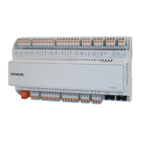
NRK16/A (with NSA) NRK16-B/A (with NSA)
Types
NRK16/A Application controller with ten universal inputs
1)
and
two analogue, two digital and two combined outputs
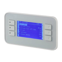
NRK16-B/A Like NRK16/A, but with panel for simple local operation
NSA Application modules, varying according to country or region,
for plugging into base units
NRK16-T../A NRK16/A + NITEL integrated communications module for a maximum
of three additional devices (see manual NT21)
NRK14-T../A Like NRK16-T../A, but without analogue outputs (see
manual NT21)
NRK16-WEB/A NRK16/A + integrated NIWEB communications module for operation
of up to 15 additional devices via the Internet (K1-07.62)
Technical data
Supply voltage Extra low voltage (SELV-E)
Nominal voltage AC 24 V, 50/60 Hz
Max. tolerance +15 / 10 %
Power consumption
Without output peripherals 3 VA
With output peripherals Max. 12 VA
Fuse Thermal element (PTC)
Supply voltage for peripheral devices
and remote operator terminal
Output voltage
DC15V ±10%, electrically isolated from AC24V
Output current Max. 150 mA
Signal inputs
2)
Universal inputs
3)
Number 10
1)
Use Can be structured as T1, Ni1000, DC 0...10 V,
digital volt-free, or for connection of NMID
Input impedance Ri (pull-up resistor) = 10 kW to DC +15 V or
100 kW to GND (change-over, see p. 6)
Remote control input
Use
Can be structured as T1, Ni1000, DC 0 ... 10 V,
min. 1.5 sink, digital volt-free contacts, or NMID
Input impedance Ri (pull-up resistor) = 10 kW to DC +15 V
Signal outputs
2)
Digital outputs
Number 2
Signal DC 0 / 24 V, 20 / +15 %
Source current Max. 50 mA
Analogue outputs
Number 2
Range DC 0 ... 10 V
Source/sink current Max. 2 mA
Technical data continued on page 2
Electrical protection
The power supply is overload-protected
with a PTC thermal element.
All DC voltages are electrically isolated
from the AC 24 V input.
All the inputs are protected against over-
voltage (max. AC/DC 45 V). Low-pass fil-
ters prevent fluctuations in measurement.
All outputs are sustained short-circuit
proof.
High frequency interference is suppres-
sed by means of filters, or in the case of
capacitive interference, discharged via
the (earthed) housing or the TE terminal
(functional earth).
Important:
For direction connection of AC 24 V
3-wire peripheral devices, "GND"
and "NS" (^) must be connected.
NRK16/A, NRK16-B/A,
(NRK16-T../A, NRK14-T../A,
NRK16-WEB/A)
Control and interlock devices
Application controllers with
pre-programmed system-specific
application modules.
The controllers may be used
as stand-alone control and
interlock devices
for remote process control within
a management system
Especially suitable for use in small
heating, ventilation and air
conditioning systems.
1)
The NMID multiplexer enables four digital
inputs to be connected to a universal
output. (see K21-06.55). The function is
integrated by use of a structure macro.
2)
When connecting peripheral devices
with special input or output signals
(e.g. Pt100, phase cut or 3-position sig-
nals), the NTIO (NTIOS) single module
carrier or an NATU adapter can be
used. (See K21-06.50 and K21-06.52).
3)
The T1/Ni1000 supply voltage can be
disabled at the inputs (see page 5). DIP
switches are provided to switch the
inputs from T1 to Ni1000 and vice versa.







 Loading...