Technical Data
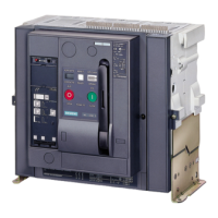
WL Circuit Breaker
WL Selection and Application Guide • 2005
1/32
Frame Rating
Frame Size II
Rated Current at 50/60 Hz A 2000 2500 3000
Rated voltage V AC 600 600 600
Operation (for operation
with LCD max 55ºC)
C
-25 / +70 -25 / +70 -25 / +70
Storage (observe special
conditions for LCD) C
-40 / +70 -40 / +70 -40 / +70
Drawout version W 500 680 1000
Fixed mount version W 230 320 450
Make-time ms 35 35 35
Break-time ms 34 34 34
Make-time, electrical
(via closing solenoid) ms
50 50 50
Break-time, electrical
(via shunt trip) ms
40 40 40
Break-time, electrical
(via instantaneous UVR) ms
73 73 73
Endurance
Mechanical operating 10,000 10,000 10,00
(without maintenance) cycles 5,000 (C-Class) 5,000 (C-Class) 5,000 (C-Class)
Electrical operating
(without maintenance) cycles
4,000 4,000 4,000
Switching frequency
operations/
hour 60 60 60
Minimum interval
between breaker trip and
next closing of the
circuit breaker (when
used with the automatic
mechanical reset of the
reclosing lockout)
ms 80 80 80
Mounting position
Dimensions Fixed-mounted width 18.1
Circuit Breaker height 18.7
depth 9.5
Guide Frame width 18.1
(for draw-out version) height 20.3
depth 18.6
Weight
Fixed-mounted Circuit Breaker 130/ 59 141 / 64 141 / 64
(w/o main busbar connectors) lb/kg 148 / 67 (C-Class) 148 / 67 (C-Class) 148 / 67 (C-Class)
177 / 80 209 / 95 209 / 95
Drawout Circuit Breaker lb/kg 220 / 100 (C-Class) 220 / 100 (C-Class) 220 / 100 (C-Class)
128 / 58 152 / 69 152 / 69
Guide Frame lb/kg 163 / 74 (C-Class) 163 / 74 (C-Class) 163 / 74 (C-Class)
Auxiliary secondary wire
Bare wire pressure 1 x AWG 14 or
size (Cu) max # of aux.
terminal (standard) 2 x AWG 16
connecting leads x cross
Tension spring terminal 2 x AWG 14
section (solid or stranded)
Ring tongue 2 x AWG 14
terminal 1 x AWG 10
2 x AWG 16
Pigtail leads (fixed mount breaker only) 1 x AWG 14, 40” long
TOC wire connection size
Bare wire pressure
(Cu) max # of aux. terminal 1 x AWG 14
connecting leads x cross
section (solid or stranded)
MOC wire connection
Bare wire pressure
size (Cu) max # of aux. terminal 1 x AWG 14
connecting leads x cross
section (solid or stranded)
Permissible ambient
temperature
Power loss at rated
current I
n
(with 3-phase
symetrical load)
Operating times
for use only with Siemens supplied ring terminals (WL10RL)
1
1
WL_SA_intro-sec1.qxd 2/7/05 1:21 PM Page 34

 Loading...