WL Circuit Breaker
1/49
WL Selection and Application Guide • 2005
Circuit Breaker Accessories
Position Signal Contact for
Guide Frame
Position signal contacts can be
retrofitted to the guide frame.
These can be used to indicate
the position of the circuit
breaker in the guide frame.
The position signal switches
are preassembled with 1.5 m
connecting cables and are
mounted on the mounting
plate. There are three contact
configurations available (see
adjacent table).
Mutual Mechanical Circuit
Breaker Interlocking
(WLNTLK)
The module for mutual
mechanical interlocking can be
implemented for two or three
WL Circuit Breakers.
The circuit breakers can be
installed either next to one
another or on top of one
another, whereby the distance
between the circuit breakers is
determined only by the length
of the Bowden wire. The
Bowden wires are available in
the standard length of 2 m.
Alternate Bowden wire lengths
of 3 m (WLNTLWRE3), 4.5 m
(WLNTLWRE4), or 6 m
(WLNTLWRE5) can be ordered
separately. Lockout signals are
forwarded over the Bowden
wires. With withdrawable circuit
breakers, the interlocking is only
effective in connected position.
The mechanical service life of
the Bowden wires is 10,000
operating cycles. For the
mutual mechanical interlocking
of circuit breakers, also see
the adjacent table.
Phase Barriers
Plant manufacturers can make
phase barriers out of insulation
material as a protection against
internal arcs. Guiding grooves
are fitted at the rear of the fixed-
mounted circuit breaker or guide
frame.
Arc Chute Cover
The arc chute cover is available as
an option for the guide frame. It
serves to protect switchgear parts
that are located directly next to
the circuit breaker.
Door Sealing Frame
and Plexiglas Cover
As standard, the WL Circuit
Breakers have IP 20 degree of
protection. However, if the
switchgear assembly is to be
provided with a higher degree
of protection, a door sealing
frame and a Plexiglas cover
are available for Frame Size II
and Frame Size III circuit breakers.
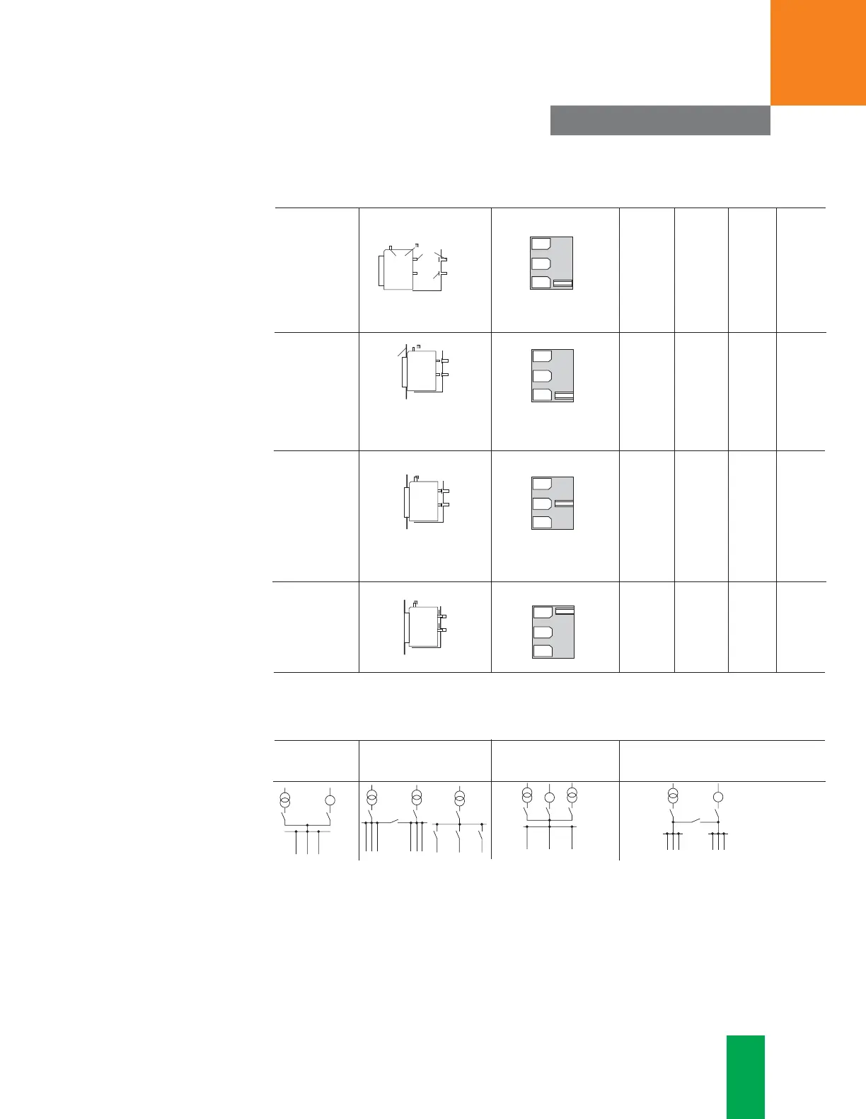
Positions of the drawout circuit breaker in the guide frame
Representation Position indicator Main Auxiliary Cubicle Shutter
circuit circuit door
Maintenance discon- discon- open closed
position nected nected
Disconnected discon- discon- closed closed
position nected nected
Test position discon- con- closed closed
nected nected
Connected con- con- closed open
position nected nected
(1) Auxiliary circuit
(2) Main circuit
(3) Cubicle door
(4) Shutter
Mutual mechanical interlocking of circuit breakers - examples
Interlocking Interlocking Interlocking Interlocking of three
of two mutual of three non-mutual of three mutual circuit breakers, two of
circuit breakers circuit breakers circuit breakers which are mutual
CONNECT
TEST
DISCON
NSE01037
CONNECT
TEST
DISCON
NSE01038
CONNECT
TEST
DISCON
NSE01039
CONNECT
TEST
DISCON
NSE01040
WL_SA_intro-sec1.qxd 2/7/05 1:26 PM Page 51
 Loading...


