Sierra Wireless
®
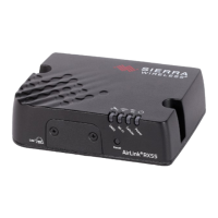
RV55 Quick Start Guide
Page 1
Reset
© 2019 Sierra Wireless All Rights Reserved PN 5304539 Rev. 1
This guide provides instructions for quickly getting your Sierra Wireless
®
AirLink
®
RV55 router configured and connected.
For more information refer to the:
• AirLink RV55 Hardware User Guide
• AirLink RV55 Software Configuration User Guide
Both are available for download from the Sierra Wireless web site (source.sierrawireless.com). Click sign up to register for free.
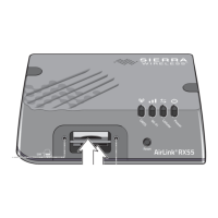
STEP 1 Install the SIM Cards
STEP 2 Connect and Turn On the Router
SIM card slot 2 (lower)
SIM card slot 1 (upper)
1. Use a #1 Phillips screwdriver to remove the SIM card cover.
2. Slide the SIM cards into the SIM card slots until they click into place.
By default, the SIM card in slot 1 (the upper slot) is the Primary SIM card. When the RV55 is
powered on or reboots, it automatically connects to the network associated with the Primary
SIM card.
3. Re-attach the cover.
NOTE: Remote ACEmanager access is disabled by default for security. If required, enable it remotely using ALMS or locally using ACEmanager (Services >
ACEmanager) and change the default password (Admin > Change Password).
1. Connect Cellular, Diversity and
GNSS antennas (if applicable).
4. Connect a Windows
®
computer to the router with an
Ethernet cable. If required by your application, connect
the RS-232 port and / or the USB port.
3. Connect 9 – 36 VDC.
To operate the router between 7 – 36 V,
after startup, launch ACEmanager, go to
Services > Power Management, and adjust
the low voltage standby settings.
NOTE: If you want to configure all your routers at the same time using AirLink Management Service, follow the instructions on page 2 to
register your routers before applying power.
2. Connect the Dual Wi-Fi antennas
(if applicable).
Sierra Wireless strongly recommends that you always ground the chassis using the unpainted mounting hole. For more information, refer to the
RV55 Hardware User Guide.
1. If not using an AC adapter, Ignition Sense must be connected to
vehicle ignition or the positive terminal of your power supply.
Black (GND)
Green (GPIO) Optional
White (Ignition Sense)
1
Red (Power)