input connections will cause permanent damage to the inverter which is not covered under
warranty. Always check polarity before making connections to the inverter.
The inverter contains capacitors that may produce a spark when first connected to battery.
Do not mount in a confined a battery or gas compartment.
Ensure the inverter is off before disconnecting the battery cables, and that AC power is
disconnected from the inverter input.
3.4 PV Wiring
CAUTION: Before connecting to PV modules, please install separately a DC circuit breaker between
the inverter and PV modules.
The PV terminal pins can accept cable size up to 8AWG, and the torque for the screws is 1.6Nm.
Max. PV Array Open Circuit Voltage is 450Vdc, pls make sure Open circuit Voltage (Voc) of PV modules
does not exceed 450V.
Please follow below steps to implement PV module connection:
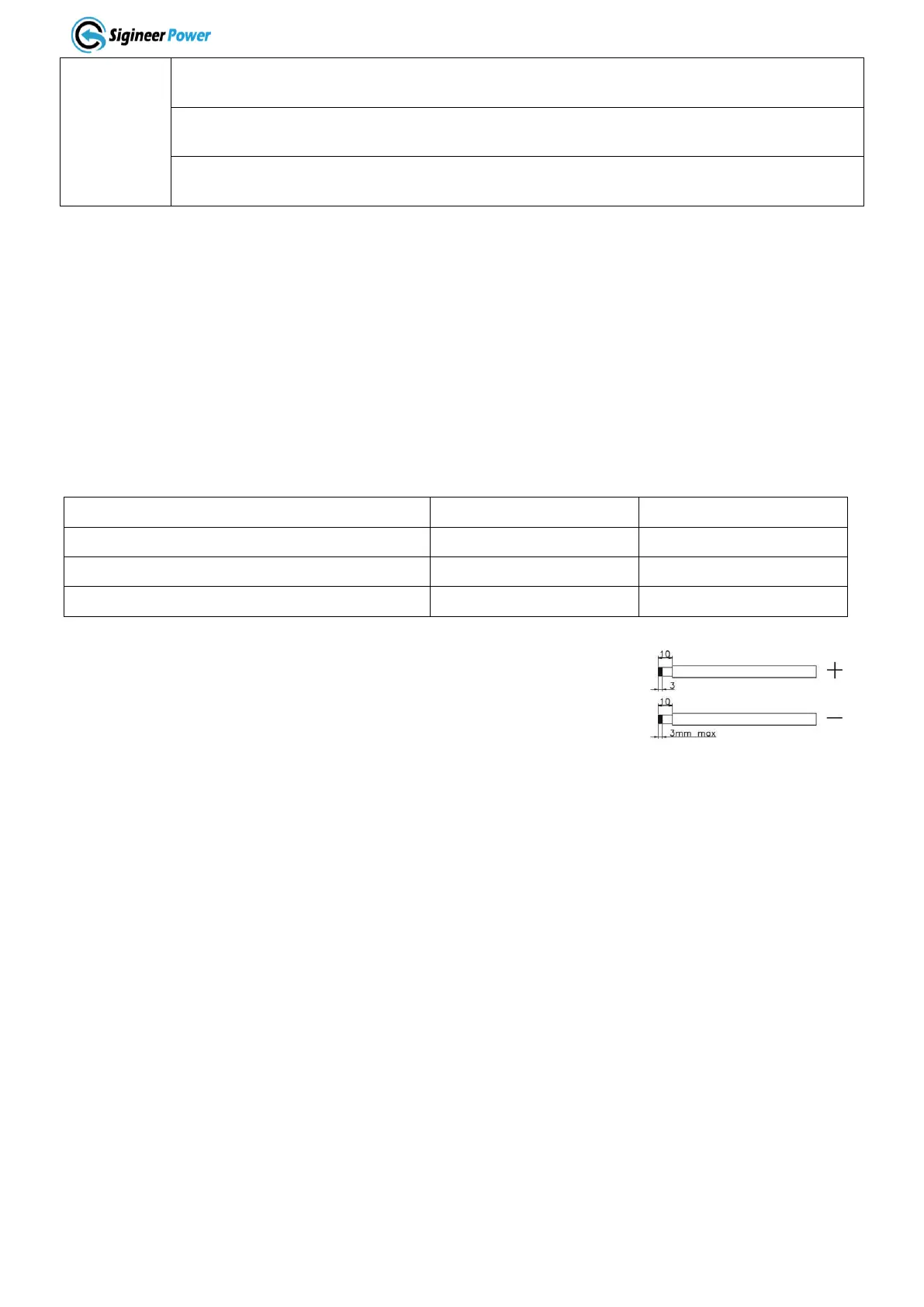
1.
Remove insulation sleeve 10 mm for positive and negative conductors.
2.
Check correct polarity of connection cable from PV modules and
PV input connectors. Then, connect positive pole (+) of
connection cable to positive pole (+) of PV input connector.
Connect negative pole (-) of connection cable to negative pole (-)
of PV input connector.
3.
Make sure the wires are securely connected.
Don’t reverse the PV input polarity or damage will occur.
3.5 AC Wiring
CAUTION!! Before connecting to AC input power source, please install a separate AC breaker between
inverter and AC input power source. This will ensure the inverter can be securely disconnected during
maintenance and fully protected from over current of AC input. The recommended spec of AC breaker is
50A for 5KVA.
CAUTION!! There are two terminal blocks with “IN” and “OUT” markings. Please do NOT mis-connect
input and output connectors.
WARNING! All wiring must be performed by a qualified personnel.
WARNING! It’s very important for system safety and efficient operation to use appropriate cable for AC
input connection. To reduce risk of injury, please use the proper recommended cable size as below.
 Loading...