Never cut the telephone cable when the cable is attached to inverter and battery is connected to the inverter.
Even if the inverter is turned off. It will damage the remote PCB inside if the cable is short circuited during
cutting.
2.5.8 LED Indicator & LCD
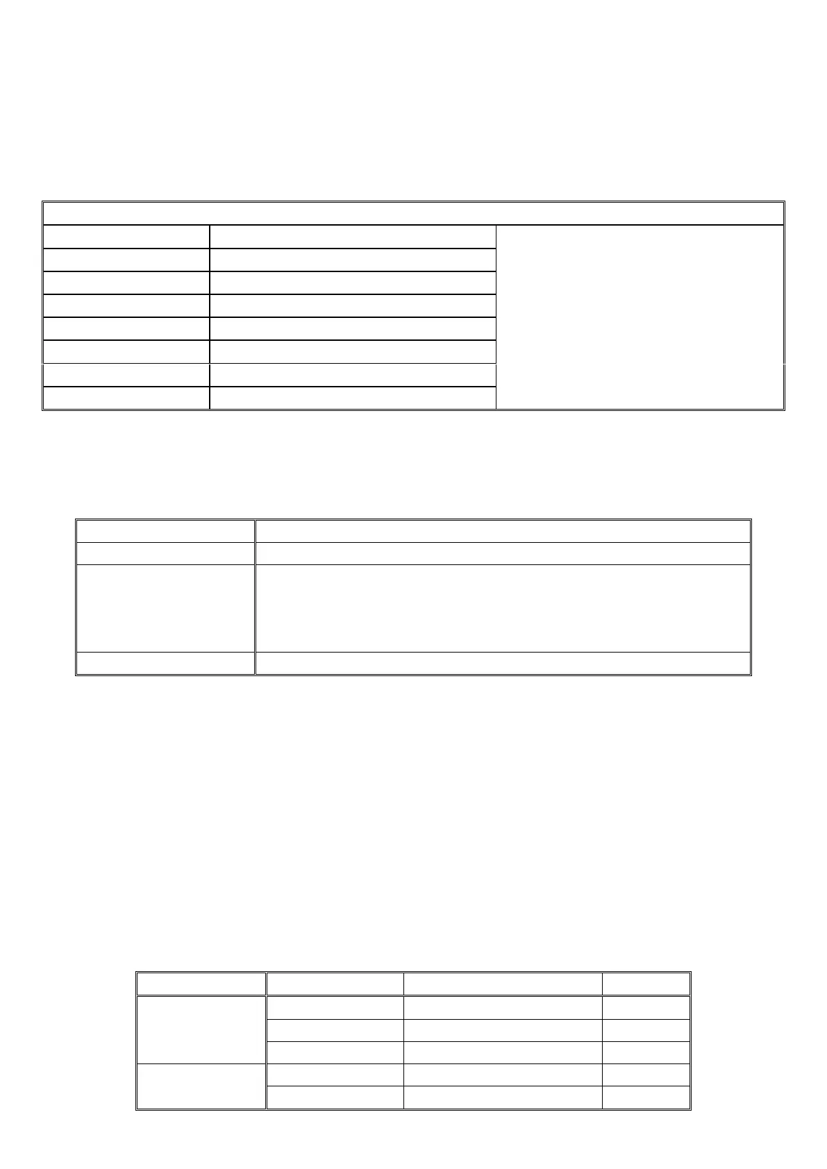
Table 2.5.7 TPH Series LED Indicators
Please refer to ‘Indicator and Buzzer’
for the detailed information.
GREEN LED lit in Inverter Mode
YELLOW LED lit in Fast Charging Mode
GREEN LED lit in Float Charging Mode
RED LED lit in Error State
RED LED lit in Over Temperature
GREEN LED lit in Power Saver Mode
2.5.9 Audible Alarm
Table 2.5.9 TPH Series Audible Alarm Spec
Inverter green LED lit, and the buzzer beeps 0.5s every 5s.
Inverter green LED lit, and the buzzer beeps 0.5s every 1s and Fault after 60s.
(1)110%<load<125%(±10%), No audible alarm in 14 minutes,
Beeps 0.5s every 1s in 15
th
minute and Fault after 15 minutes;
(2)125% <load<150%(±10%), Beeps 0.5s every 1s and Fault after 60s;
(3)Load>150%(±10%), Beeps 0.5s every 1s and Fault after 20s;
Heat-sink temp. ≥105ºC, Over temp red LED Lighting, beeps 0.5s every 1s;
2.5.10 FAN Operation
For 1-3KW, there is one multiple controlled DC fan,For 4-6KW, there is two multiple controlled DC fan
which starts to work according to the following logic
For 8-12KW, there is two multiple controlled DC fan and one AC fan. The DC fan will work in the same
way as the one on 1-3KW, while the AC fan will work once there is AC output from the inverter.
So when the inverter is in power saver mode, the AC fan will work from time to time in response to the
pulse sent by the inverter in power saver mode.
The Operation of the DC fan at the DC terminal side is controlled by the following logic
(Refer to Table 2.5.10):
Table 2.5.10 TPH Series Fan Operation Logic
 Loading...