For 12Vdc Battery Mode (*2 for 24Vdc Mode ; *4 for 48Vdc Mode)
De-sulphation
The de-sulphation cycle on switch position 8 is marked in red because this is a very dangerous setting if you
do not know what you are doing. Before ever attempting to use this cycle you must clearly understand what
it does and when and how you would use it.
What causes sulphation? This can occur with infrequent use of the batteries(nor), or if the batteries have
been left discharged so low that they will not accept a charge. This cycle is a very high voltage charge cycle
designed to try to break down the sulfated crust that is preventing the plates taking a charge and thus allow
the plates to clean up and so accept charge once again.
Charging depleted batteries
The TPH series inverter allows start up and through power with depleted batteries.
For 12VDC model, after the battery voltage goes below 10V, if the switch is still (and always) kept in "ON"
position, the inverter is always connected with battery, and the battery voltage does not drop below 2V, the
inverter will be able to charge the battery once qualified AC inputs are present.
Before the battery voltage goes below 9VDC, the charging can be activated when the switch is turned to
“Off”, then to “ON”.
When the voltage goes below 9VDC, and you accidently turn the switch to OFF or disconnect the inverter
from battery, the inverter will not be able to charge the battery once again, because the CPU loses memory
during this process.
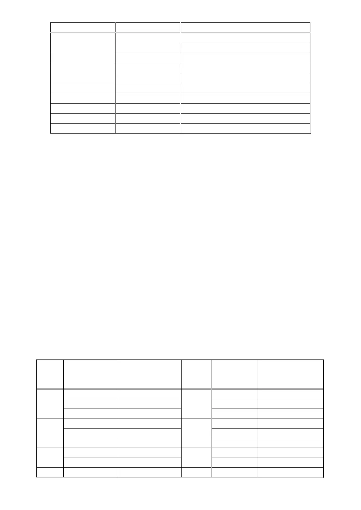
Table 2.5.3 AC Charging Current for TPH model
 Loading...