Do you have a question about the SIGLENT SPD3303C Series and is the answer not in the manual?
| Channels | 3 |
|---|---|
| Output Voltage (CH1/CH2) | 0-30 V |
| Output Current (CH1/CH2) | 0-3 A |
| Output Current (CH3) | 0-3 A |
| Output Power (CH1/CH2) | 90 W |
| Interface | USB, RS232 |
| Operating Temperature | 0°C to 40°C |
| Storage Temperature | -20°C to 70°C |
| Output Power | 195W |
| Voltage Resolution | 10 mV |
| Ripple & Noise (CV) | < 1 mVrms |
| Ripple & Noise (CC) | < 3 mArms |
| Temperature Coefficient (CV) | ≤ 100 ppm/°C |
| Temperature Coefficient (CC) | ≤ 100 ppm/°C |
| Display | LCD |
| Power Rating | 50/60Hz |
| Output Voltage (CH3) | 2.5V/3.3V/5V (Fixed) |
| Current Resolution | 1mA (CH1/CH2), 1mA (CH3) |
| Load Regulation (CV) | ≤0.01% + 2mV |
| Line Regulation (CV) | ≤0.01% + 2mV |
Use only the power cord designed for the instrument and authorized by local country.
Details AC input voltages (100V/110V/220V/230V ±10%) and frequency (50/60Hz).
Use correct fuse types (T6.3A/250V for 100V/110V, T3.15A/250V for 220V/230V).
Ensure the protective terra conductor is connected to earth to avoid electric shock.
Read the guide carefully to know details about ratings before connection.
Keep proper ventilation and check fans/air vents regularly to prevent overheating.
Specifies location, humidity, altitude, and temperature for operation.
Avoid operating the instrument in an explosive atmosphere to prevent injury or damage.
Keep the product surface clean and dry to maintain performance.
Defines DANGER, WARNING, and CAUTION terms used in the manual.
Illustrates common safety symbols found on the product.
Highlights key features like three output channels, power compatibility, save/recall, and PC software control.
Steps for inspecting the shipping container, instrument, and accessories upon arrival.
Important checks and requirements before operating the SPD3303C.
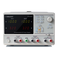
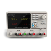
Identifies and describes the main components and layout of the front panel.
Explains the specific functions of buttons for parameter setting, channel control, etc.
Details the output and ground terminals located on the front panel.
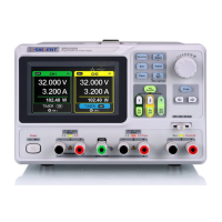
Explains the components of the user interface display, including channel logos, voltage, and current values.
Identifies and describes components on the rear panel, such as warning message, DIP switch, AC power socket, and USB interface.
Steps to check if the output voltage is adjustable and within the specified range.
Steps to check if the output current is adjustable and within the specified range under short circuit.
Provides an overview of the SPD3303C's three independent outputs and their voltage options.
Details how to operate CH1 and CH2 in independent mode.
Explains the operation of the CH3 output channel.
Describes how to link CH1 and CH2 in series mode for increased voltage.
Describes how to link CH1 and CH2 in parallel mode for increased current.
Explains how to save and recall instrument settings.
Guide to upgrading instrument firmware using PC software via USB.
Alternative method for firmware upgrading if the normal method fails.
Lists SCPI commands for remote control of the power supply.
Provides detailed explanations for SCPI commands like *IDN?, *SAV, *RCL.
Addresses common issues and provides solutions for the power supply.
Details the voltage and current ranges for different output modes.
Covers power change rate, load change rate, ripple, noise, and recovery time.
Lists specifications for power/load change rates, ripple, and noise.
Specifies track error for master/no load conditions.
Details power/load change rates and ripple/noise for parallel operation.
Lists power/load change rates and ripple/noise for series operation.
Specifies display resolution and measurement accuracy for voltage and current.
Details insulation resistance requirements between terminals and power cord.
Defines conditions for altitude, temperature, humidity, and installation.
Defines conditions for storage temperature and humidity.
Covers AC power supply requirements, volume, and weight.