GREEN – once the device is initialized, the GREEN LED state represents the IDLE state.
Operational States:
ALTERNATING RED/GREEN – when the device is actively transmitting data.
GREEN – Device is idle
RED – Indicates a failure. Usually indicates no 10 GbE connection to PC.
OFF – Device has lost power
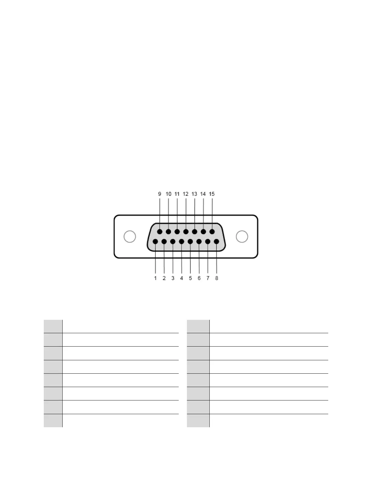
2.5.3 GPIO Port
On the front panel of the SM200/SM435 there is a DB15 port which provides up to 8 digital logic
lines available for immediate read inputs, or output lines as immediate write pins, or configurable
through the API to be able to switch during a sweep based on frequency.
Front panel female DB15 port on SM200
2.5.3.1 Pinout
 Loading...