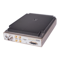
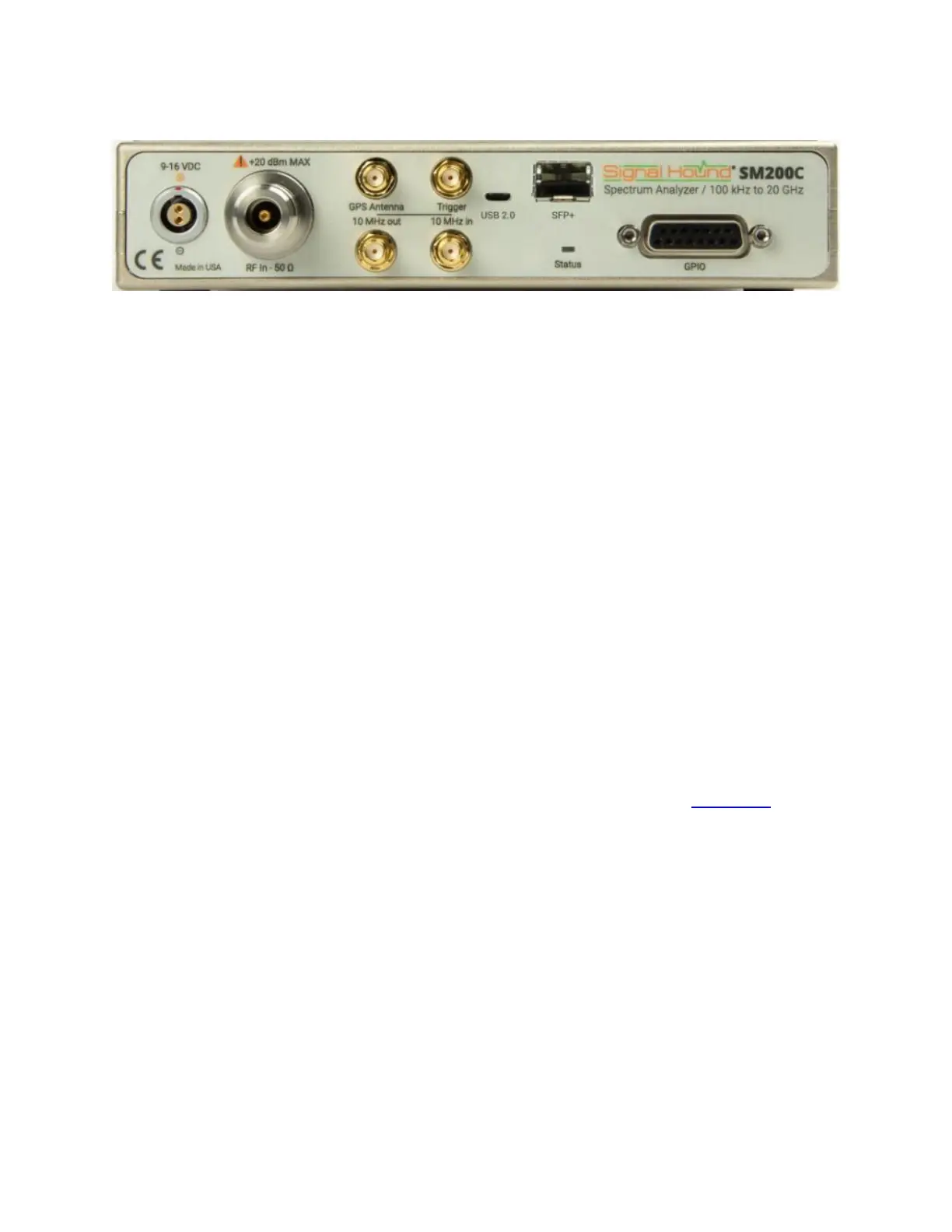
1. 9-16V DC power input: Use the included 12V supply, or a battery that can source 40 watts.
2. 50Ω type N RF Input: Do not exceed +20 dBm or damage may occur.
3. SMA GPS antenna port: The GPS antenna (included) may be connected here to discipline
the time base and time stamp I/Q data
4. Trigger In: The rising or falling edge of a digital 3.3V or 5V signal may be used to trigger
in I/Q streaming modes.
5. 10 MHz out: Use to synchronize external equipment requiring a 10 MHz input
6. 10 MHz in: Disciplines internal timebase to an external 10 MHz source. 0 to +15 dBm
recommended.
7. USB 2 connector: Only used for firmware upgrades.
8. SFP+ connector: 10 GbE bi-directional data connection to the PC, using an optical SFP+
module and fiber optic cable.
9. GPIO port (DB15): Can be used to control external equipment, such as an external
antenna switch. Commands may be embedded within a sweep. See GPIO Port for more
information.
10. Status LED: Alternates red/green as commands are processed and sweeps are
generated.
2.5.2.1 LED States
The possible SM200C LED states are OFF, RED, GREEN, and ALTERNATING. All combinations
of device and LED state are described below.
Initialization States:
OFF – until the power cable is connected.
ORANGE/RED – during device initialization once the power is connected.
 Loading...