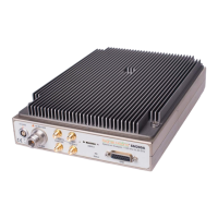
5. 10 MHz out: Use to synchronize external equipment requiring a 10 MHz input
6. 10 MHz in: Disciplines internal timebase to an external 10 MHz source. 0 to +15 dBm
recommended.
7. USB 3 connector with locking screws for Vision cable: Data connection to PC. Both power
supply and USB must be connected for device to power on.
8. GPIO port (DB15): Can be used to control external equipment, such as an external
antenna switch. Commands may be embedded within a sweep. See GPIO Port for more
information.
9. Status LED: Alternates red/green as commands are processed and sweeps are
generated.
2.5.1.1 LED States
The possible SM200A/B LED states are OFF, RED, GREEN, and FLASHING. All combinations
of device and LED state are described below.
Initialization States:
OFF – until the power cable and USB cable are both connected.
ORANGE/RED – during device initialization once the power and USB cables are connected.
GREEN – once the device is initialized, the GREEN LED state represents the IDLE state.
Operational States:
ALTERNATING RED/GREEN – when the device is actively transmitting over USB 3.0.
GREEN – Device is idle
RED – Indicates a failure, such as exceeding maximum operating temperature
OFF – Device has lost power
2.5.2 SM200C Front Panel
The front panel has 9 connectors:
 Loading...