EasyManua.ls Logo

Signet 8900 User Manual

Signet 8900
52 pages
To Next Page IconTo Next Page
Page #1 background imageLoading...
Page #1 background image
Signet 8900 Multi-Parameter Controller
Multi-Parameter
Controller
C1 2.50 µS/cm
F2 58.43 GPM
Relay 1
Relay 2
ENTER
3-8900.090-1
3-8900.090-1 Rev. J 07/10 English
Contents
1. Speci cations 2
2. Description 4
2.1 Compatibility 4
2.2 System Overview 5
3. Installation and Basic Functionality 6
3.1 Unpacking 6
3.2 Tools and Equipment Required 6
4. Plug-in Modules 6
4.1 I/O Module 7
4.2 Power Module 7
4.3 Output Module 8
4.4 Relay Module 8
4.5 8059 External Relay Module 9
5. Mounting the Base Unit 10
5.1 Panel Mounting 10
5.2 Mounting Accessories 11
6. Wiring 12
6.1 Signal Type: Frequency 12
6.2 Digital (S
3
L) Input wiring 13
6.2.1 Digital Cable Length Calculations 14
6.2.2 Digital Cable Routing Diagrams 15
6.3 Power Module (3-8900.402-X) 17
6.4 Output Module (3-8900.405-X) 17
6.5 Relay Module (3-8900.403-X) 18
6.6 8059 External Relay Module 18
7. Operational Overview 19
7.1 General Operation Flowchart 19
7.2 System Con guration 20
7.3 Menu Directory 20
8. System Setup Menu 21
8.1 System Setup: Channel Type 21
8.2 Automatic Sensor Recognition 22
8.3 Automatic Channel Assignment 22
8.4 Automatic Display Con gurations 22
8.5 Other Automatic Displays 23
8.6 Displays for Derived Functions 23
9. Channel Settings 24
Important Safety Information
Read and understand instruction manual before using
this product.
This unit is designed to be connected to equipment
which can be hazardous to persons and property if
used incorrectly. Read and understand all associated
equipment manuals and safety warnings before using
with this product.
Do not remove rear panel slot shields if the modules
are not installed.
Remove power to unit before wiring input and output
connections.
Wiring connections to this product should only be
performed by quali ed personnel.
Do not exceed published speci cations in the use of
this product.
In case of communication error or loss of source
signal:
Relays will be deactivated.
Current outputs will go to 22.1 mA.
Voltage outputs will go to 0 V.
9.1 Channel Settings: Flow 24
9.2 Channel Settings: pH 25
9.3 Channel Settings: ORP 25
9.4 Channel Settings: Conductivity 26
9.5 Channel Settings: Pressure 27
9.6 Channel Settings: Temperature 27
9.7 Channel Settings: Level 28
9.8 Channel Settings: OTHER (4–20) 30
10. Hold Inputs 30
11. Relay Mode Descriptions 31
11.1 Relay Setup Menu 33
11.2 Advanced Relay Mode 34
12. Output 35
13. Calibration 36
13.1 Calibration: Flow 36
13.2 Calibration: pH 37
13.3 Calibration: ORP 37
13.4 Calibration: Conductivity 38
13.5 Calibration: Pressure 38
13.6 Calibration: Temperature 38
13.7 Calibration: Level 38
14. Options 39
14.1 Password Security 39
Appendix A: Derived Functions 40
Appendix B: Level System Con guration 41
Appendix C: Conductivity & Temp Comp 43
Appendix D: USP Limits 44
Appendix E: Cloning using Digital (S
3
L) 45
Appendix F: BTU Quick Start Guide 47
Appendix G: 8900 display messages 48
Ordering Information 52

Table of Contents

Question and Answer IconNeed help?

Do you have a question about the Signet 8900 and is the answer not in the manual?

Signet 8900 Specifications

General IconGeneral
BrandSignet
Model8900
CategoryController
LanguageEnglish

Summary

1. Specifications

General Specifications

Technical details on input, measurement types, relays, and general system capabilities.

Dimensions

Physical size and mounting panel requirements of the controller unit.

Enclosure and Display Features

Information on case material, gasket, window, keypad, and display characteristics.

Electrical Specifications

Power requirements for AC and DC modules, and output power to sensors.

2. Description

2.1 Compatibility

Lists compatible sensors and external relays for the 8900 system.

2.2 System Overview

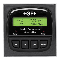
Describes the basic system components and their arrangement in the enclosure.

3. Installation and Basic Functionality

3.1 Unpacking

Lists items included with the 8900 base unit and unpacking instructions.

3.2 Tools and Equipment Required

Lists necessary tools for installation and panel mounting.

4. Plug-in Modules

4.1 I/O Module

Details on I/O module types, functionality, and connections for sensor inputs and outputs.

4.2 Power Module

Information on AC and DC power modules for the 8900 controller.

4.3 Output Module

Describes optional output modules for analog signals (4-20mA, 0-5/10VDC).

4.4 Relay Module

Details on optional internal relay modules (dry-contact and solid-state).

4.5 External Relay Module

Information on optional external relay modules for expanded relay capabilities.

5. Mounting the Base Unit

5.1 Panel Mounting

Instructions and requirements for mounting the 8900 in a panel cutout.

5.2 Mounting Accessories

Details on accessories like splashproof covers, panel adapters, and wall mount brackets.

6. Wiring

6.1 Signal Type: Frequency

Explains frequency input wiring, cable length, and sensor compatibility.

6.2 Digital (S³L) Input Wiring

Instructions for wiring digital (S³L) sensors, including daisy-chaining.

6.2.1 Digital Cable Length Calculations

Guides for calculating maximum digital bus cable length based on current and gauge.

6.2.2 Digital Cable Routing Diagrams

Illustrates various wiring configurations for digital (S³L) sensors.

6.3 Power Module Wiring

Diagrams showing AC and DC power module connections.

6.4 Output Module Wiring

Wiring diagrams for analog output modules (4-20mA, 0-5/10VDC).

6.5 Relay Module Wiring

Wiring for internal relay modules (solid-state and dry-contact).

6.6 8059 External Relay Module Wiring

Wiring for external relay modules connected via the digital bus.

7. Operational Overview

Keypad Functions

Explains the function of each keypad button in different operational modes.

7.1 General Operation Flowchart

Illustrates the navigation between the 8900's display modes and menus.

7.2 System Configuration

Details how to view installed modules and configure the system.

7.3 Menu Directory

Describes accessing the main system menus like Setup, Channel Settings, etc.

8. System Setup Menu

8.1 System Setup: Channel Type

Guides the user through assigning specific measurement types to input channels.

8.2 Automatic Sensor Recognition

Explains how the 8900 detects and lists connected digital sensors upon startup.

8.3 Automatic Channel Assignment

Describes how sensors are automatically assigned to channels based on type and hierarchy.

8.4 Automatic Display Configurations

Details how displays are automatically configured for each channel type.

8.5 Other Automatic Displays

Covers additional displays for totalizers, analog outputs, and relay status.

8.6 Displays for Derived Functions

Explains how results from derived functions are displayed.

9. Channel Settings

9.1 Channel Settings: Flow

Configuration options for flow channels, including units, K-Factor, and totalizers.

9.2 Channel Settings: pH

Configuration options for pH channels, including units, setpoints, and averaging.

9.3 Channel Settings: ORP

Configuration options for ORP channels, including setpoints and averaging.

9.4 Channel Settings: Conductivity

Configuration options for conductivity channels, including units, TDS, and temp compensation.

9.5 Channel Settings: Pressure

Configuration options for pressure channels, including units, setpoints, and averaging.

9.6 Channel Settings: Temperature

Configuration options for temperature channels, including units and averaging.

9.7 Channel Settings: Level

Configuration options for level channels, including units, percentage display, and offset.

9.8 Channel Settings: Other (4-20)

Configuration for channels using a 4-20mA input signal, such as dissolved oxygen.

10. Hold Inputs

Hold Time and Input Settings

Options for setting hold duration and managing held input states for process control.

11. Relay Mode Descriptions

Relay Mode Overview

General description of internal and external relay operating modes like Low, High, Window.

11.1 Relay Setup Menu

Detailed settings for configuring individual relays (source, mode, setpoints, hysteresis, delay).

11.2 Advanced Relay Mode Logic

Explains programming relays using multiple conditions and Boolean logic operators.

12. Output

Output Configuration Settings

Settings for assigning sources, ranges, and test operations for analog outputs.

13. Calibration

13.1 Calibration: Flow

Procedures for volumetric and rate-based calibration of flow channels to determine K-Factor.

13.2 Calibration: pH

Procedures for calibrating pH sensors using standard and slope methods.

13.3 Calibration: ORP

Procedures for calibrating ORP sensors using standard and slope methods.

13.4 Calibration: Conductivity

Procedures for calibrating conductivity and temperature sensors.

13.5 Calibration: Pressure

Procedures for zero and pressure calibration of pressure sensors.

13.6 Calibration: Temperature

Procedures for calibrating temperature sensors.

13.7 Calibration: Level

Procedures for calibrating level sensors.

14. Options

Configuration Options

Settings for contrast, auto scroll, function types, cloning, language, and memo.

14.1 Password Security

Information on standard/enhanced passwords and reset procedures for security.

Appendix A: Derived Functions

Derived Function Types

Explains calculations for Ratio, Difference, Sum, Passage, Reject, and Recovery.

Appendix B: Level System Configuration

Level Measurement Setup

Defines zero reference point, sensor location, offset, and level measurement concepts.

Level and Volume Conversion

Details custom vessel configuration and technical references for level/volume calculations.

Appendix C: Conductivity/Resistivity Application

Conductivity and Resistivity Details

Explains temperature effects, compensation, TDS factor, and calibration procedures.

Appendix D: USP Limits

Using the USP Function

Describes how to use USP limits for pharmaceutical water conductivity monitoring.

Appendix E: Cloning using Digital (S³L)

Controller Designation and Wiring

Steps for designating controllers and wiring them for data cloning.

Cloning Process Configuration

Steps for configuring and executing the cloning process between controllers.

Appendix F: BTU Quick Start Guide

BTU Calculation Setup

Guide for configuring the 8900 to calculate Power and Energy (BTU) from flow and temperature.

Appendix G: 8900 Display Messages

Display Message Reference

Lists and describes various messages displayed by the 8900 for user notification.

Ordering Information

Product Ordering Guide

Lists part numbers, codes, and descriptions for ordering units and accessories.