7 Signet 8900 Multi-Parameter
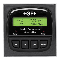
4.1 I/O Module, required; install one (1)
Mfr. Part No. Description
3-8900.401-1 Two inputs, no outputs
3-8900.401-2 Two inputs, two passive 4 to 20 mA outputs
3-8900.401-3 Two inputs, two active 4 to 20 mA outputs
3-8900.401-4 Two inputs, two 0 to 5/10 VDC outputs
3-8900.401-5 Four inputs, no outputs
3-8900.401-6 Four inputs, two passive 4 to 20 mA outputs
3-8900.401-7 Four inputs, two active 4 to 20 mA outputs
3-8900.401-8 Four inputs, two 0 to 5/10 VDC outputs
3-8900.401-9 Six inputs, no outputs
3-8900.401-10 Six inputs, two passive 4 to 20 mA outputs
3-8900.401-11 Six inputs, two active 4 to 20 mA outputs
3-8900.401-12 Six inputs, two 0 to 5/10 VDC outputs
• These modules determine the maximum number of sensor input channels
available for the instrument. The 8900 will detect all connected sensors
at startup and assign channels up to the maximum available on the I/O
Module.
• Optional analog outputs are contained on the I/O Module, and will always
be identifi ed as Outputs 1 & 2 in the 8900 menus. Any and all analog
outputs are freely assignable to any channel. All analog outputs available
from the 8900 are isolated.
3-8900.621C
I/O Module 3-8900.401-X
1
2
3
4
5
6
7
8
9
10
11
12
13
14
+5VDC (Black)
Freq. Input (Red)
GND (Shield)
+5VDC (Black)
Freq. Input 2 (Red)
S L (Red)
GND (White/Shield)
+5VDC (Black)
S L (Red)
GND (White/Shield)
3
3
Analog Output 1
Analog Output 2
(if applicable)
(if applicable)
Frequency
Input
1
Frequency
Input 2
OR
S
3
L
Input
2
S
3
L
Input
1
+
-
+
-
3-8900.621C
I/O Module 3-8900.401-X
1
2
3
4
5
6
7
8
9
10
11
12
13
14
+5VDC (Black)
Freq. Input (Red)
GND (White/Shield)
+5VDC (Black)
Freq. Input 2 (Red)
S L (Red)
GND (White/Shield)
+5VDC (Black)
S L (Red)
GND (White/Shield)
3
3
Analog Output 1
Analog Output 2
(if applicable)
(if applicable)
Frequency
Input
1
Frequency
Input 2
OR
S
3
L
Input
2
S
3
L
Input
1
+
-
+
-
3-8900.620
100 - 240VAC
50-60Hz, 24V
A MAX
~
11 - 24VDC
0.7 A MAX.
N
L
+
-
Power Connectio
n
DO NOT attempt to c
onnect both
AC and DC at the same time
C
NO
NC
NO
NC
C
Solid State
Relays
Rating:
50mA 30V
Mechanical Relay
s
Rating:
5A 250 V
AC
5A 30 VDC
~
+
-
+
-
~
CAUTION
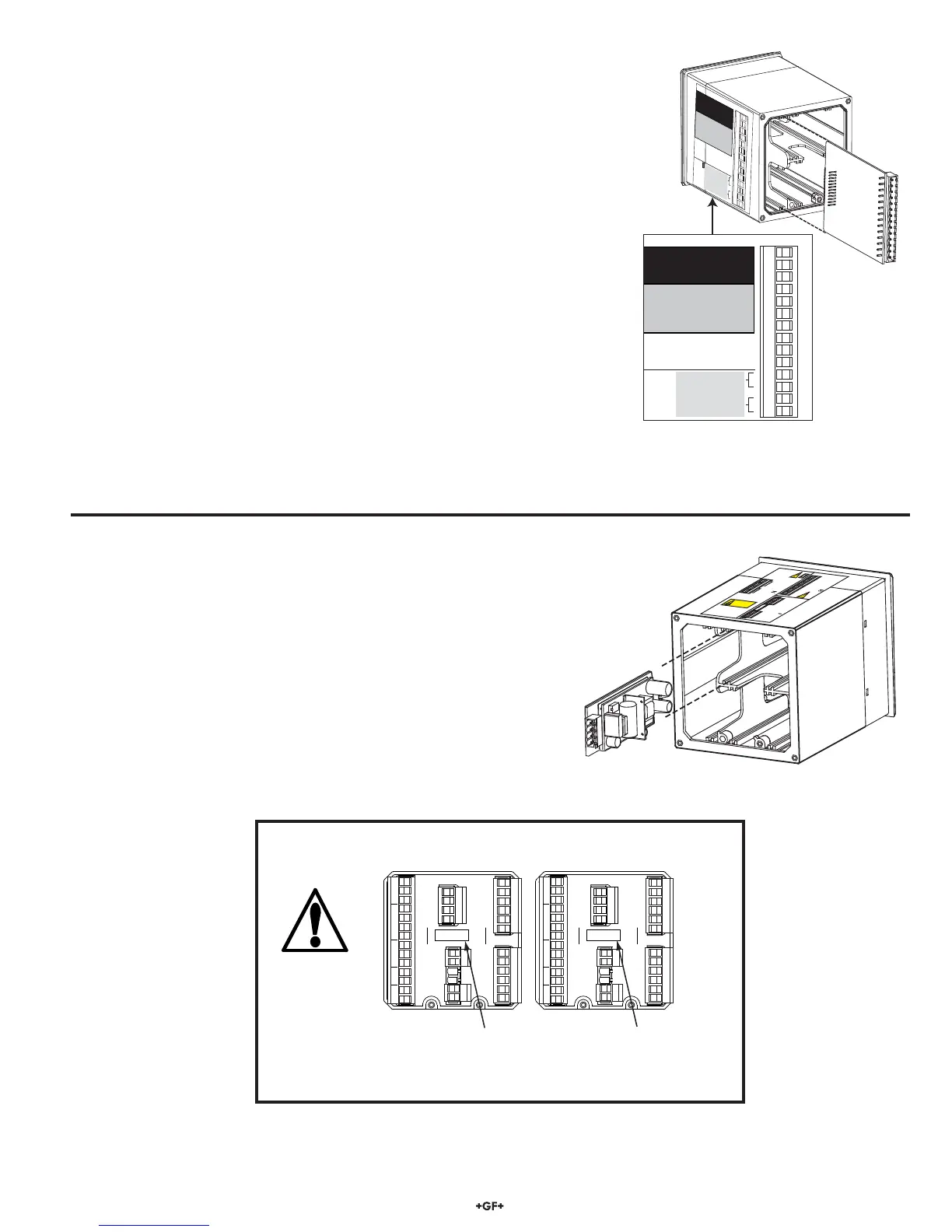
4.2 Power Module, required; install one (1)
Mfr. Part No. Description
3-8900.402-1 85 to 264 VAC, 50/60 Hz
3-8900.402-2 12 to 24 VDC ±10%
• Each 8900 Base Unit may be powered with either AC or DC voltage, but not both
simultaneously (no "uninterruptible" power option).
• The AC Power Module is universal; no jumper selection is required.
OUT 2 OUT 1
POWER
COMM PORT /
OUT 4 OUT 3
RELAY 2 RELAY 1
RELAY 4 RELAY 3
SENSOR INPUTS
C
NO
NC
NO
NC
C
C
NO
NC
NO
NC
C
N
L
+
-
AC ONLY
+
-
+
-
1
2
3
4
5
6
7
8
9
10
11
12
13
14
OUT 2 OUT 1
POWER
COMM PORT /
OUT 4 OUT 3
RELAY 2 RELAY 1
RELAY 4 RELAY 3
SENSOR INPUTS
C
NO
NC
NO
NC
C
C
NO
NC
NO
NC
C
N
L
+
-
DC ONLY
+
-
+
-
1
2
3
4
5
6
7
8
9
10
11
12
13
14
For additional operator safety, an adhesive power indication label
(AC ONLY or DC ONLY) is packaged with each Power Module
and should be applied to the 8900 rear panel as illustrated.
IMPORTANT SAFETY INFORMATION
 Loading...